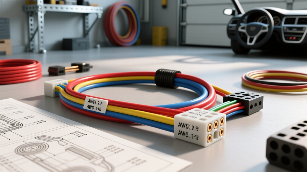
The Danger of Guessing Wire Size in 12V Systems
When fabricating custom harnesses, adding off-road lighting, or upgrading fuel delivery systems, guessing your wire gauge is a fast track to electrical fires, melted bulkhead connectors, and erratic ECU behavior. Unlike 120V household AC systems, 12V DC automotive systems require massive amperage to deliver the same wattage, making voltage drop and thermal runaway critical concerns. To engineer a safe and reliable circuit, you must systematically apply an automotive wiring gauge chart to match your specific load, wire length, and operating environment. This practical installation guide walks you through the exact process professional automotive electricians use to size, route, and terminate 12V and 24V circuits.
Step 1: Calculate True Circuit Amperage and Duty Cycle
Before consulting any sizing charts, you must determine the maximum current draw of your component and its duty cycle. Components like cooling fans, fuel pumps, and winches have two distinct amperage ratings: inrush (startup) and continuous.
- Continuous Load: Components that run for extended periods (e.g., a Walbro 450lph fuel pump drawing 18A continuously, or heated seats). These require wire sized for 100% of the rated amperage plus a 20% safety margin.
- Intermittent Load: Components that run in short bursts (e.g., starter solenoids, power windows, or horn relays). These can tolerate slightly higher voltage drop because the wire does not have time to reach thermal saturation.
For our installation example, we will be wiring a 130A continuous-duty off-road LED light bar. Because it is a continuous load, we must size the wire to handle at least 156A safely, or utilize a relay-based dual-circuit system to manage the high amperage safely.
Step 2: Measure Total Wire Run Length (The Hidden Variable)
The most common mistake DIYers make when using an automotive wiring gauge chart is measuring only the distance from the battery to the component. In a DC circuit, the ground return path is just as critical as the positive feed. You must calculate the total circuit length (Positive Wire Length + Ground Wire Length).
If your battery is in the trunk and your light bar is on the front bumper, the positive run might be 18 feet. If you ground the light bar to the chassis near the bumper, and the chassis ground path back to the battery negative terminal is another 18 feet, your total circuit length for the voltage drop calculation is 36 feet. Ignoring the ground return path will result in undersized wire, severe voltage drop, and dim lighting or slow motor operation.
Step 3: Apply the Automotive Wiring Gauge Chart
With your total amperage and total circuit length established, reference the chart below. This chart is based on the SAE J1128 standard for automotive primary wire, assuming a maximum allowable voltage drop of 3% (0.36V on a 12V system) in a high-temperature under-hood environment.
| AWG Size | Max Amps (Chassis / 80°C) | Max Amps (Engine Bay / 125°C) | Ohms per 1,000 ft (Copper) | Recommended Inline Fuse |
|---|---|---|---|---|
| 18 AWG | 10A | 6A | 6.38 Ω | 5A - 7.5A |
| 16 AWG | 15A | 10A | 4.01 Ω | 10A - 15A |
| 14 AWG | 20A | 15A | 2.52 Ω | 15A - 20A |
| 12 AWG | 30A | 20A | 1.58 Ω | 20A - 25A |
| 10 AWG | 45A | 30A | 0.99 Ω | 30A - 40A |
| 8 AWG | 65A | 45A | 0.62 Ω | 50A - 60A |
| 6 AWG | 95A | 65A | 0.39 Ω | 70A - 80A |
| 4 AWG | 125A | 95A | 0.24 Ω | 100A - 120A |
| 2 AWG | 170A | 125A | 0.15 Ω | 150A |
| 1/0 AWG | 245A | 170A | 0.09 Ω | 200A - 225A |
Note: For high-amperage runs exceeding 10 feet, always step up one gauge size to compensate for voltage drop. Consult resources like the Del City automotive wire catalog for exact stranding counts and outer diameter specifications to ensure your wire fits through factory firewall grommets.
Step 4: Select SAE-Approved Insulation and Connectors
Never use standard PVC-insulated building wire (THHN) in a vehicle. Automotive environments subject wiring to extreme heat, vibration, and chemical exposure (oil, brake fluid, road salt). You must use cross-linked polyethylene (XLPE) insulated wire, specifically GXL, TXL, or HDT grades.
- GXL (General Cross-Linked): Standard wall thickness, excellent for general chassis routing and high-temp engine bay areas.
- TXL (Thin-wall Cross-Linked): Thinner insulation, ideal for wrapping in harness loom where space and weight are at a premium. Rated to 125°C.
- HDT (Heavy-Duty Thermoplastic): Thicker PVC insulation, best for heavy battery cables and high-vibration areas where abrasion resistance is critical.
Termination and Crimping Specifications
Soldering is generally discouraged in high-vibration automotive applications because it creates a rigid point that can cause the wire to fatigue and snap just behind the solder joint. Instead, use a high-quality ratcheting crimper. For connectors, utilize adhesive-lined marine-grade heat shrink terminals. The inner adhesive melts and seals the wire strands, preventing capillary action from drawing moisture and causing green copper corrosion. Match the terminal barrel color to your gauge: Red (22-18 AWG), Blue (16-14 AWG), and Yellow (12-10 AWG).
Step 5: Execute the Relay and Fuse Integration
For any circuit drawing over 15A, or any circuit triggered by a low-amperage switch (like an ECU output or a dashboard toggle), you must use a Bosch-style automotive relay. This allows you to run heavy-gauge wire directly from the battery to the load, while using lightweight 18 AWG wire for the control circuit.
Standard 5-Pin Relay Wiring Pinout
- Pin 30 (Common Power): Connect to the battery positive via an inline fuse. Use the heavy gauge dictated by your automotive wiring gauge chart (e.g., 10 AWG for a 30A circuit).
- Pin 87 (Normally Open Output): Connect to the positive terminal of your component. Use the same heavy gauge as Pin 30.
- Pin 86 (Coil Power): Connect to a switched 12V ignition source or dashboard toggle switch. 18 AWG is sufficient here.
- Pin 85 (Coil Ground): Connect to a clean, bare-metal chassis ground. 18 AWG.
- Pin 87a (Normally Closed): Leave disconnected and insulated unless you are building a specific changeover circuit (e.g., switching between high and low beam headlights).
Real-World Troubleshooting: Voltage Drop and Thermal Runaway
Even with the correct gauge, poor installation practices can mimic the symptoms of undersized wire. If your custom fuel pump is losing pressure under heavy load, or your LED light bar is flickering, perform a voltage drop test while the circuit is under load. Set your multimeter to DC Volts, place the red probe on the battery positive post, and the black probe on the component's positive terminal. A reading higher than 0.3V indicates excessive resistance in the positive feed. Repeat the test on the ground side (battery negative post to component housing).
Common Failure Modes to Avoid
- Melted Bulkhead Connectors: Running high-amperage grounds through factory multi-pin firewall connectors instead of establishing a dedicated, bolted chassis ground. Always drill a dedicated hole, sand away the powder coat or paint to bare metal, and use a star washer to bite into the chassis.
- Thermal Runaway at Crimps: Using non-ratcheting pliers to crimp heavy-gauge terminals (like 4 AWG ring terminals). A loose crimp increases electrical resistance, generating heat. This heat further increases resistance in a destructive feedback loop, eventually melting the terminal and causing a fire.
- Shared Ground Loops: Grounding high-draw components (like an aftermarket fuel pump) to the same chassis stud as sensitive ECU sensors. The high current returning to the battery can elevate the ground plane voltage, causing the ECU to read inaccurate sensor data and trigger lean/rich codes.
By rigorously applying an automotive wiring gauge chart and adhering to SAE installation standards, you ensure your custom electrical upgrades are safe, reliable, and capable of handling the harsh realities of the automotive environment.