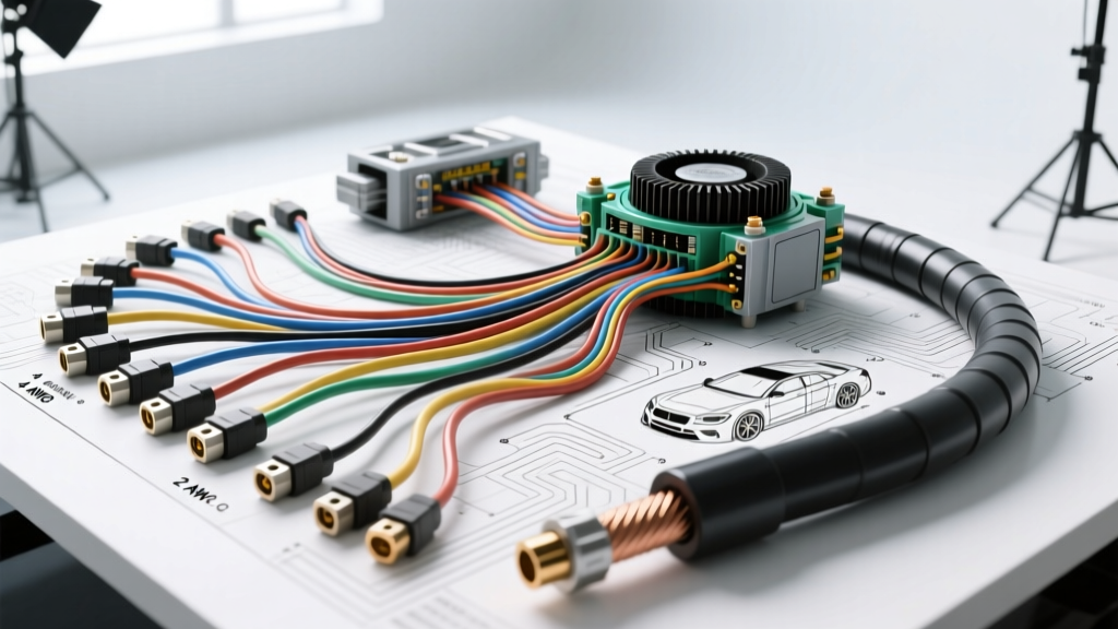
The Physics of Voltage Drop in Modified Vehicles
When enthusiasts add high-draw accessories—such as massive car audio amplifiers, off-road lighting arrays, or electric water pumps—the factory charging system quickly reaches its limit. Swapping to a 200A or 300A high-output alternator is the standard fix, but this introduces a critical bottleneck: the factory wiring harness. Most OEM alternator charge wires are 8 AWG or 10 AWG, designed strictly for 100A to 140A loads. Pushing 250A through an 8 AWG wire results in severe voltage drop, excessive heat generation, and potentially catastrophic electrical fires. To safely unlock the potential of a high-amp alternator, you must integrate a larger gauge wire into your vehicle's charging circuit, commonly known as the 'Big Three' wiring upgrade.
Metallurgy Matters: OFC vs. CCA in Larger Gauge Wire
Before selecting your wire, you must understand the metallurgical differences between Oxygen-Free Copper (OFC) and Copper-Clad Aluminum (CCA). Many budget-friendly 'big wire' kits sold online use CCA. While CCA wire looks identical to copper on the outside, its aluminum core has significantly higher electrical resistance. According to the Allied Wire and Cable AWG specifications, aluminum conducts electricity at only about 61% of the efficiency of pure copper.
If you use CCA wire, you must step up to an even larger gauge wire to achieve the same ampacity as OFC. For automotive high-amp applications, always insist on 100% OFC wire that meets SAE J1127 battery cable standards. OFC wire features a higher strand count, making it vastly more flexible and resistant to the constant engine bay vibrations that cause brittle aluminum cores to snap internally over time.
AWG Sizing and Voltage Drop Reference Chart
Choosing the correct larger gauge wire depends on the maximum amperage of your alternator and the total length of the wire run (positive and negative combined). The following chart outlines the maximum continuous ampacity and the expected voltage drop over a 10-foot total circuit run at 14.4V.
| Wire Gauge (AWG) | Strand Count (OFC) | Max Continuous Amps | Voltage Drop (10ft run @ Max Amps) | Best Application |
|---|---|---|---|---|
| 4 AWG | 1050 | 150A | 0.38V | Stock Alternator Replacement / Minor Audio |
| 2 AWG | 1680 | 200A | 0.32V | 200A Alternator / Moderate Winch Use |
| 1 AWG | 2100 | 250A | 0.30V | 250A Alternator / Heavy Audio & Lighting |
| 1/0 AWG | 2660 | 300A | 0.28V | 300A+ Alternator / Big Three Upgrade Standard |
| 2/0 AWG | 3360 | 350A+ | 0.25V | Dual Alternator Setups / EV Conversions |
Note: For runs exceeding 15 feet, or for environments with high ambient under-hood temperatures exceeding 125°C, always step up to the next larger gauge wire to compensate for thermal resistance.
Executing the Big Three Upgrade
The 'Big Three' upgrade involves replacing or supplementing the three most critical ground and power paths in the engine bay. Using 1/0 AWG OFC wire is the gold standard for most high-output alternator swaps.
1. Alternator Positive to Battery Positive
The factory charge wire must be bypassed or supplemented. Route a 1/0 AWG red OFC wire directly from the alternator's main output stud to the positive battery post. Critical Warning: Do not remove or upgrade the OEM 'sense' wire (typically an 18 AWG or 16 AWG wire, often red with a white or yellow stripe, plugged into the alternator's voltage regulator pigtail). The regulator uses this thin sense wire to monitor actual battery voltage. If you upgrade the sense wire or tie it directly to the alternator output, the regulator will read artificially high voltage and undercharge the battery.
2. Engine Block to Chassis Ground
High-amperage starters and alternators rely on the engine block as a primary ground return path. Factory braided ground straps are notorious for corroding and snapping. Install a 1/0 AWG black OFC wire from a clean, bare-metal point on the engine block (such as an unused intake manifold bolt or dedicated ground boss) directly to the chassis frame rail. Use a star washer between the ring terminal and the bare metal to bite through any microscopic oxidation, ensuring a zero-resistance bond.
3. Battery Negative to Chassis Ground
The final leg completes the circuit back to the battery. Run a second 1/0 AWG black wire from the negative battery terminal to a dedicated, paint-free grounding point on the chassis or strut tower. In heavily modified vehicles, adding a secondary ground busbar tied to this larger gauge wire is highly recommended to manage localized ECU and sensor grounds.
Fusing, Routing, and Firewall Pass-Throughs
Running a larger gauge wire without proper overcurrent protection is a severe safety hazard. Because 1/0 AWG wire can handle upwards of 300A, a standard MAXI fuse will not suffice. You must install an ANL or Class-T fuse on the positive charge wire.
- ANL Fuses: Ideal for alternator-to-battery runs. Select an ANL fuse rated 10% to 15% higher than your alternator's maximum rated output (e.g., a 250A ANL fuse for a 220A alternator).
- Routing: Never route the positive charge wire parallel to the factory ECU sensor harnesses to avoid electromagnetic interference (EMI). If crossing is unavoidable, cross at a strict 90-degree angle.
- Firewall Pass-Throughs: If routing the larger gauge wire into the cabin for a rear-mounted battery or audio capacitor, you must use a heavy-duty rubber firewall grommet. Apply dielectric grease to the wire before pushing it through the grommet to prevent the rubber from binding, tearing, and eventually chafing the wire insulation against the steel firewall.
Terminal Crimping and Torque Specifications
A common failure mode in custom wiring projects is relying on screw-down 'clamp' terminals or poorly executed crimps. For 1/0 AWG and larger, you must use a hydraulic crimper with the correct hexagonal die. According to Painless Performance technical guidelines, a proper hex crimp cold-welds the copper strands to the terminal barrel, creating a gas-tight seal that prevents moisture intrusion and internal corrosion.
After crimping, seal the terminal barrel with dual-wall, adhesive-lined heat shrink (typically 3/8" or 1/2" diameter). The inner thermoplastic adhesive melts and flows into the wire strands, creating a waterproof barrier against battery acid and road salt.
Hardware and Torque Specs:
- Alternator Output Stud (Typically M8 or 5/16"): 8 - 10 Nm (6 - 7.5 lb-ft). Do not overtighten, as the alternator casing is cast aluminum and the stud can strip easily.
- Battery Post Clamps (M8/M10 side posts or top post adapters): 10 - 12 Nm (7.5 - 9 lb-ft). Ensure the ring terminal is stacked below any secondary OEM accessories but above the locking washer.
- Chassis Ground Bolts (Typically M10): 25 - 30 Nm (18 - 22 lb-ft) to ensure the star washer bites firmly into the chassis steel.
Voltage Drop Testing: Troubleshooting Decision Tree
Once the larger gauge wire is installed, you must validate the circuit using a digital multimeter (DMM) set to DC Volts. A voltage drop test measures the exact amount of voltage lost due to resistance across the wire and connections while the circuit is under load.
- Step 1: Start the vehicle and turn on all high-draw accessories (headlights, HVAC blower on max, rear defroster) to force the alternator into maximum output.
- Step 2 (Positive Side Test): Place the red DMM probe on the alternator output stud and the black probe on the positive battery post.
- Result < 0.20V: Circuit is healthy. The larger gauge wire is performing optimally.
- Result 0.20V - 0.50V: Marginal. Check for loose crimps, undersized ring terminal holes causing contact on only one side of the stud, or a failing ANL fuse holder.
- Result > 0.50V: Critical failure. Immediate re-evaluation of wire gauge, terminal crimps, and connection cleanliness is required.
- Step 3 (Negative Side Test): Place the red DMM probe on the alternator casing (bare metal) and the black probe on the negative battery post.
- Result < 0.10V: Engine-to-chassis and battery-to-chassis grounds are excellent.
- Result > 0.10V: Ground path restriction. Remove the ground bolts, sand the mating surfaces down to bare, shiny metal with 80-grit sandpaper, apply a thin layer of conductive anti-seize, and re-torque.
By meticulously selecting the correct larger gauge wire, utilizing OFC metallurgy, and executing aerospace-grade terminations, your high-amp alternator upgrade will deliver stable, cool, and reliable voltage to every electrical system in your modified vehicle.