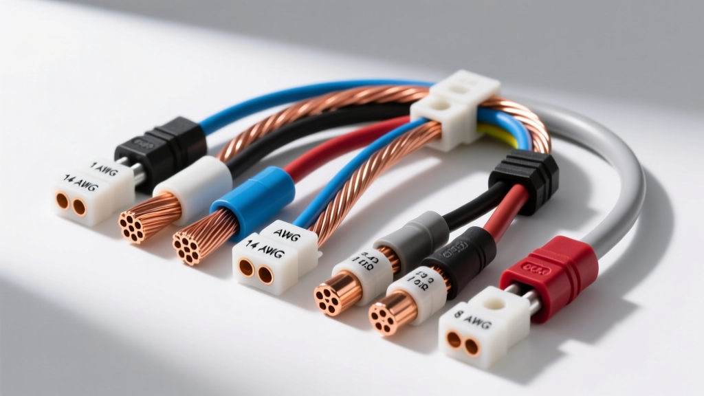
Why a Wire Gauge Resistance Table Matters in 12V Automotive Systems
In automotive electrical systems, voltage drop is the silent killer of performance. Whether you are wiring a high-output alternator, upgrading a fuel pump for forced induction, or installing a trunk-mounted audio amplifier, the physical size of the wire (AWG) is only half the equation. The true metric of performance is electrical resistance. A comprehensive wire gauge resistance table is an indispensable tool for any automotive electrician, allowing you to predict voltage loss, manage heat dissipation, and ensure sensitive ECU sensors receive clean, uncorrupted signals.
Unlike residential 120V/240V alternating current (AC) systems, a vehicle operates on a 12V to 14.4V direct current (DC) architecture. At these low voltages, even a fraction of an ohm of unwanted resistance can result in catastrophic voltage drop, leading to dimming headlights, sluggish starter motors, or erratic transmission shift solenoids. To make informed decisions, professionals must cross-reference wire gauge against material composition, stranding, and operating temperature.
Material Showdown: Oxygen-Free Copper (OFC) vs. Copper Clad Aluminum (CCA)
The most critical mistake enthusiasts make when consulting a standard wire gauge resistance table is assuming all wires of the same AWG share identical resistance. They do not. The market is flooded with Copper Clad Aluminum (CCA) wire, which features an aluminum core coated with a thin layer of copper. While CCA is lighter and cheaper, its electrical resistance is significantly higher than pure Oxygen-Free Copper (OFC).
Aluminum has roughly 61% the conductivity of copper. Consequently, a 4 AWG CCA wire will exhibit nearly 40% more resistance per foot than a 4 AWG OFC wire. If you use a standard copper-based resistance table to size a CCA wire for a 150-amp car audio amplifier, you will experience severe voltage drop and potential thermal runaway at the crimp terminals. When selecting wire for high-current automotive applications, always verify the conductor material before applying resistance calculations.
The Master Wire Gauge Resistance Table (AWG 18 to 1/0)
The following table compares standard automotive wire sizes, highlighting the stark resistance differences between pure copper and CCA alternatives. Resistance values are measured in Ohms per 1,000 feet at 20°C (68°F). Ampacity ratings are based on SAE J1128 standards for single-conductor chassis wiring in high-temperature engine bay environments.
| AWG Size | Stranding | OFC Resistance (Ω/1k ft) | CCA Resistance (Ω/1k ft) | Max Amps (Chassis 105°C) |
|---|---|---|---|---|
| 18 AWG | 16/30 | 6.385 | 10.150 | 6A - 10A |
| 16 AWG | 26/30 | 4.016 | 6.380 | 10A - 14A |
| 14 AWG | 41/30 | 2.525 | 4.010 | 15A - 20A |
| 12 AWG | 65/30 | 1.588 | 2.520 | 20A - 25A |
| 10 AWG | 105/30 | 0.9989 | 1.580 | 30A - 40A |
| 8 AWG | 168/30 | 0.6282 | 0.995 | 40A - 55A |
| 6 AWG | 266/30 | 0.3951 | 0.625 | 60A - 75A |
| 4 AWG | 420/30 | 0.2485 | 0.395 | 85A - 105A |
| 2 AWG | 665/30 | 0.1563 | 0.248 | 120A - 150A |
| 1/0 AWG | 1064/30 | 0.0983 | 0.156 | 170A - 200A |
Note: Data derived from standard conductivity metrics and cross-referenced with NFPA 70 National Electrical Code (NEC) Chapter 9, Table 8 for baseline DC resistance parameters.
Real-World Selection Scenarios: Matching Wire to the Circuit
Scenario A: High-Current Alternator and Starter Upgrades
When upgrading to a 200-amp alternator for an off-road vehicle or a high-draw electric power steering (EPS) swap, the main power and ground cables must be sized to minimize voltage drop. Using the table above, a 15-foot run of 1/0 AWG OFC wire yields a total loop resistance (30 feet total for power and ground) of approximately 0.0029 ohms. At 150 amps of continuous draw, the voltage drop is a mere 0.43 volts. If CCA wire were used, the drop would increase to 0.68 volts, which can cause the alternator's internal voltage regulator to overcompensate, leading to premature diode failure. For these high-amperage runs, always use fine-strand OFC wire terminated with closed-end copper ring terminals, crimped with a hydraulic or heavy-duty ratcheting tool, and sealed with adhesive-lined dual-wall heat shrink.
Scenario B: Low-Voltage Sensor and ECU Circuits
High-current circuits aren't the only victims of resistance. Modern engine management systems rely on 5-volt reference signals for sensors like the Throttle Position Sensor (TPS) and Mass Air Flow (MAF) sensor. These circuits typically utilize 18 AWG or 20 AWG TXL (Thin Cross-Linked) wire. While the amperage is negligible (usually under 50 milliamps), the ECU measures voltage drops in the millivolt range. A poor crimp or a corroded pin in a Molex MX150 or Delphi Packard Weather-Pack connector can introduce 5 to 10 ohms of resistance. This micro-resistance will skew the 5V reference down to 4.6V, causing the ECU to read an inaccurate throttle angle, resulting in hesitation or a limp-mode trigger. For sensor circuits, prioritize high-quality copper stranding and gold-plated connector pins over sheer wire thickness.
Calculating Voltage Drop Using Resistance Data
To properly utilize a wire gauge resistance table, you must calculate the total voltage drop for your specific application. The formula for DC voltage drop is:
Voltage Drop = Current (Amps) × Total Wire Resistance (Ohms)
Crucial Step: Total wire resistance must account for the entire circuit loop (the positive wire from the battery to the load, PLUS the negative ground wire from the load back to the chassis/battery).
Example Calculation: You are wiring a 255 LPH in-tank fuel pump in a trunk-mounted fuel cell. The pump draws 12 amps under load. The distance from the front-mounted battery to the trunk is 12 feet. The total loop length is 24 feet (0.024 thousand feet).
- Using 12 AWG OFC: 0.024 × 1.588 Ω = 0.038 ohms total resistance. Voltage drop = 12A × 0.038Ω = 0.45 volts. (Acceptable; pump receives ~13.5V).
- Using 12 AWG CCA: 0.024 × 2.520 Ω = 0.060 ohms total resistance. Voltage drop = 12A × 0.060Ω = 0.72 volts. (Marginal; pump receives ~13.2V, reducing flow rate).
For critical fuel delivery systems, always select a wire gauge that limits voltage drop to less than 3% of the system voltage (less than 0.42V on a 14V system).
Insulation Types and Temperature Derating
A wire gauge resistance table provides baseline metrics at 20°C (68°F). However, under-hood temperatures routinely exceed 100°C (212°F). Copper is a positive temperature coefficient (PTC) material, meaning its electrical resistance increases as it gets hotter. For every 1°C increase above 20°C, copper's resistance increases by approximately 0.39%.
This thermal reality dictates your choice of insulation. Standard PVC wire (rated for 85°C) will become brittle and melt near exhaust headers. Automotive professionals specify Cross-Linked Polyethylene (XLPE) insulation types defined by SAE J1128:
- TXL (Thin Wall): Rated to 125°C. Ideal for general chassis and interior harnesses.
- GXL (General Wall): Rated to 125°C. Slightly thicker insulation for added abrasion resistance.
- SXL (Special Wall): Rated to 125°C. Thickest insulation, used in high-vibration, high-heat areas near the engine block.
When routing 8 AWG or 6 AWG power wires through the firewall and near the exhaust manifold, the ambient heat will increase the wire's resistance. To compensate for this thermal derating, it is standard practice to step up one AWG size (e.g., use 6 AWG instead of 8 AWG) for engine bay routing to maintain the target voltage drop.
Expert Troubleshooting: When Resistance Lies
Even if you select the perfect wire gauge using a resistance table, real-world failures often occur at the termination points. A common diagnostic trap is measuring voltage at the battery (showing 14.2V) and assuming the load is receiving adequate power. Instead, use a digital multimeter (DMM) set to DC Volts to measure the voltage drop across the wire while the circuit is under load. Place the positive probe on the battery terminal and the negative probe directly on the load's power pin. Any reading above 0.2V indicates excessive resistance in the wire or the crimp.
Furthermore, standard DMMs cannot accurately measure the milliohm resistance of heavy-gauge battery cables. To properly diagnose a suspected high-resistance 1/0 AWG starter cable, technicians use a dedicated micro-ohmmeter or perform a loaded voltage drop test during engine cranking. If the voltage drop across a 3-foot 1/0 AWG cable exceeds 0.1V while pulling 300 amps, the cable has internal strand corrosion or a failing terminal crimp, regardless of what the wire gauge resistance table dictates it should be. Always inspect crimps for strand fraying and ensure no insulation is trapped inside the terminal barrel, which acts as a dielectric barrier and drastically spikes circuit resistance.