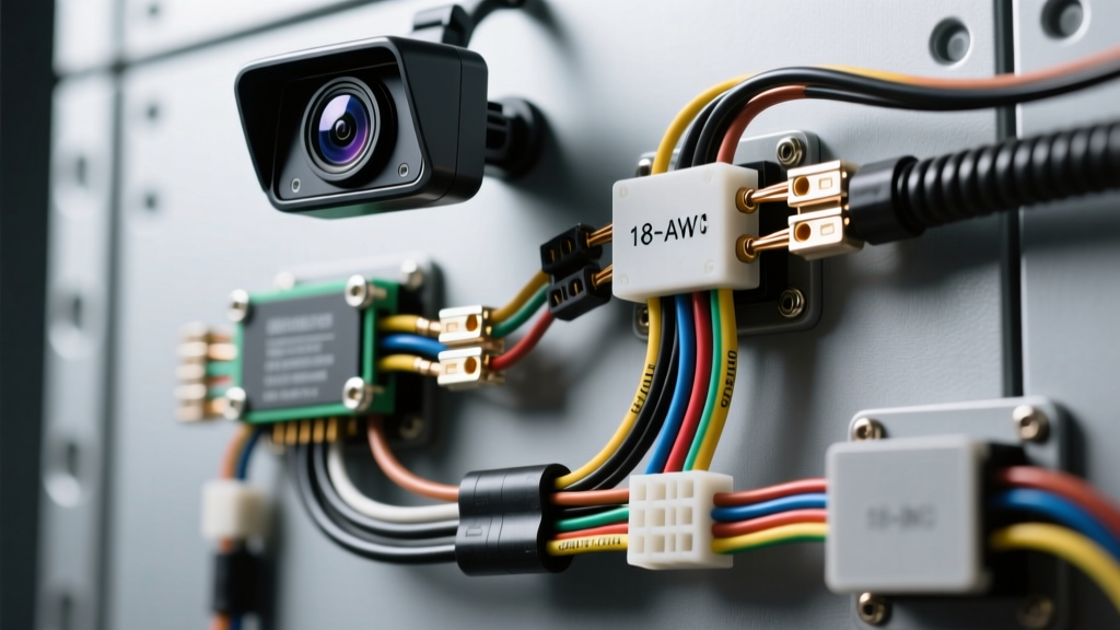
The "Generic" Reverse Camera Wiring Diagram Trap
When integrating aftermarket vision systems, relying on a generic reverse camera wiring diagram is one of the most frequent causes of catastrophic electrical failure. Modern vehicles utilize complex multiplexed networks, Pulse Width Modulation (PWM) lighting circuits, and sensitive CAN-bus architectures. A diagram that worked perfectly on a 2008 Honda Civic will likely fry a body control module (BCM) or trigger a dashboard Christmas tree of warnings on a 2020 Ford F-150 or BMW 3-Series.
As automotive electrical systems evolve, installers must move beyond simple 12V tap-and-go methodologies. This guide dissects the most dangerous mistakes found in amateur and outdated reverse camera wiring diagram implementations, providing actionable safety warnings, specific wire gauge requirements, and diagnostic protocols to ensure a safe, noise-free installation.
Catastrophic Mistake 1: Tapping PWM Reverse Light Circuits
The most common error when following a basic reverse camera wiring diagram is tapping the 12V trigger wire (typically red, 18-AWG) directly into the vehicle's reverse light bulb wire. In older vehicles, this wire carries a steady 12V DC when the transmission is shifted into reverse. However, most modern European and domestic vehicles use Pulse Width Modulation (PWM) to monitor bulb health and extend filament life.
A PWM circuit rapidly switches the 12V supply on and off. While a multimeter might read an average of 9V to 11V RMS, the peak voltage remains 12V, and the signal is essentially a square wave. When you feed this square wave into the camera's internal Linear Dropout (LDO) voltage regulator or the head unit's trigger circuit, it causes severe voltage ripple. The result is a flickering camera feed, head unit reboots, or a blown BCM output driver due to inductive kickback.
The Safe Solution: PWM Filter or Automotive Relay
Never connect a camera trigger directly to a PWM circuit. You have two safe options:
- 12V DC Relay Bypass: Use the reverse light wire to trigger the coil (Pin 85/86) of a standard Bosch-style 30A automotive relay. Connect the camera's 12V trigger to the switched output (Pin 87), drawing steady 12V DC from a fused accessory circuit (Pin 30). This isolates the sensitive camera electronics from the vehicle's PWM monitoring system.
- PWM to DC Filter Module: Install a dedicated 12V PWM filter (often containing a rectifier diode, a 1000µF smoothing capacitor, and a voltage regulator). This converts the square wave into a clean, steady 12V DC output capable of supplying the 250mA-500mA required by most aftermarket CMOS or CCD cameras.
Catastrophic Mistake 2: RCA Shield Grounding and Loop Isolation
A standard reverse camera wiring diagram will show the RCA video cable running from the rear camera to the front head unit. What diagrams rarely explain is the nature of the RCA cable's copper braided shield. The shield acts as the signal ground (return path) for the analog video signal, not a chassis ground.
If you ground the camera's power wire to the rear chassis, and the head unit is grounded to the front chassis, you create a ground loop. The vehicle's alternator introduces AC ripple onto the chassis ground. Because the front and rear grounds are at slightly different electrical potentials, this AC ripple travels through the RCA shield, manifesting as rolling horizontal hum bars or severe alternator whine on the display.
Safety & Quality Protocol
To comply with SAE J1113 Electromagnetic Compatibility Standards regarding analog signal integrity, you must maintain a single-point ground or use isolation. If a ground loop occurs, install an inline RCA Ground Loop Isolator. This device uses a 1:1 broadband transformer (typically rated for 10Hz to 100kHz bandwidth) to physically break the DC continuity of the RCA shield while allowing the high-frequency composite video signal to pass via magnetic induction.
4-Pin M12 Aviation Connector Pinout Reference
For heavy-duty, commercial, or RV installations, standard RCA and 2-pin power pigtails are insufficient due to vibration and moisture ingress. These setups utilize a 4-pin M12 aviation connector. Miswiring this connector based on assumed color codes will instantly destroy the camera's internal microphone preamp or the head unit's audio input stage.
| Pin Number | Wire Color (Typical) | Function | AWG / Spec | Safety Warning |
|---|---|---|---|---|
| Pin 1 | Red | 12V DC Power (+) | 18-AWG | Must be fused at 2A within 6 inches of the battery/source. |
| Pin 2 | Black | Chassis Ground (-) | 18-AWG | Verify continuity to battery negative; avoid painted chassis points. |
| Pin 3 | White / Yellow | Audio / Microphone (+) | 22-AWG Shielded | Do not apply 12V to this pin; it will fry the head unit's RCA audio input. |
| Pin 4 | Green / Blue | Trigger / Reverse Signal | 20-AWG | Only connects to the 12V reverse trigger source; never to constant 12V. |
Always verify pinouts with a multimeter before mating the connector. Manufacturers frequently alter internal PCB layouts without updating external documentation. For deeper integration protocols, refer to the Mobile Electronics Certified Professional (MECP) Guidelines for commercial vehicle upfitting.
Wire Gauge and Voltage Drop Safety Chart
Many generic diagrams specify "use the included wire" or fail to mention AWG ratings altogether. The wire included with cheap eBay or Amazon camera kits is often 22-AWG or even 24-AWG copper-clad aluminum (CCA). Running 22-AWG CCA wire over a 25-foot distance in a truck or SUV will result in severe voltage drop, causing the camera's infrared (IR) night-vision LEDs to starve for current and shut down.
| Wire Gauge (AWG) | Material | Max Run (12V / 500mA Load) | Voltage Drop at 20ft | Application |
|---|---|---|---|---|
| 22-AWG | CCA (Copper-Clad Aluminum) | 6 feet | ~1.04V (10.96V delivered) | Short jumper wires only. Do not use for vehicle routing. |
| 20-AWG | OFC (Oxygen-Free Copper) | 12 feet | ~0.52V (11.48V delivered) | Minimum acceptable for trigger signals and low-draw audio. |
| 18-AWG | OFC (Oxygen-Free Copper) | 25 feet | ~0.42V (11.58V delivered) | Standard for 12V power and ground runs in sedans/crossovers. |
| 16-AWG | OFC (Oxygen-Free Copper) | 40+ feet | ~0.26V (11.74V delivered) | Required for trucks, RVs, and cameras with heavy IR LED arrays. |
According to Bosch Automotive Electronics Architecture specifications, maintaining a minimum of 11.2V at the camera's input terminals is critical for the proper initialization of the CMOS sensor and the engagement of the IR cut filter. Always use stranded OFC wire for mobile applications to resist vibration-induced work hardening and breakage.
Real-World Failure Modes & Diagnostic Decision Tree
When a system fails post-installation, use this diagnostic sequence to isolate the fault without blindly replacing components:
- Symptom: Camera feed is completely black, but head unit switches to the camera input icon.
Cause: Loss of 12V power or blown internal LDO.
Fix: Check the 18-AWG power wire at the camera pigtail with a multimeter. If 12V is present, the camera's internal voltage regulator is dead (likely caused by a voltage spike from a PWM circuit). Replace camera and install a relay bypass. - Symptom: Image displays but has severe rolling horizontal lines that increase in speed with engine RPM.
Cause: Alternator whine via RCA ground loop.
Fix: Disconnect the RCA cable from the head unit. If the lines persist on the camera's standalone monitor, the ground loop is at the camera chassis ground. If lines disappear, install an inline RCA ground loop isolator at the head unit. - Symptom: Head unit displays "No Signal" and does not switch inputs when shifted into reverse.
Cause: Trigger wire failure or CAN-bus rejection.
Fix: Verify 12V on the reverse trigger wire at the back of the head unit. If 12V is present but the radio ignores it, the head unit may require a CAN-bus interface module to authorize the reverse camera input, common in VW/Audi MQB platforms. - Symptom: Night vision is completely dark, but daytime image is fine.
Cause: Voltage drop preventing IR LED relay from engaging.
Fix: Measure voltage at the camera while in complete darkness. If voltage drops below 11V when the IR LEDs attempt to draw an extra 300mA, upgrade the power and ground runs from 18-AWG to 16-AWG OFC wire.
Conclusion
Treating a modern vehicle's electrical system like a simple 12V battery and bulb circuit is a recipe for expensive damage. By understanding the limitations of a generic reverse camera wiring diagram, respecting PWM lighting circuits, properly managing RCA signal grounds, and adhering to strict AWG requirements, you ensure a reliable, high-definition installation that integrates seamlessly with the vehicle's existing architecture.