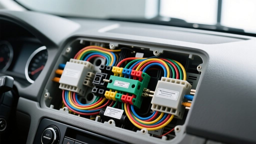
The Hidden Dangers of Covert Automotive Camera Wiring
When outfitting a vehicle for covert surveillance, fleet monitoring, or rideshare security, the term 'spy camera installation' typically refers to hidden cabin DVRs, discreet interior monitors, or anti-theft tracking modules. Unlike standard dash cams that mount visibly to the windshield, covert systems require routing cables through complex interior trim, headliners, and deep dashboard cavities. This level of concealment introduces severe electrical and safety hazards if executed improperly.
As an automotive electrical specialist, I have diagnosed countless vehicle failures stemming from poorly executed hidden camera installs. From catastrophic airbag deployment failures to fried CAN bus modules, the margin for error is razor-thin. This guide details the most critical wiring mistakes made during spy camera installations and provides the technical specifications required to execute the job safely and reliably.
Mistake #1: Routing Through Airbag Deployment Zones
The most dangerous mistake in any covert camera installation is routing power or video cables across the deployment path of the side-curtain airbag (SAB). Modern vehicles feature airbags that deploy from the roof rail down past the A, B, and C-pillars. If an 18 AWG power wire or an RG174 video cable is routed over or across the airbag curtain, the explosive force of deployment will either snap the wire, causing a short circuit, or turn the wire into a high-velocity projectile inside the cabin.
The Correct A-Pillar Routing Procedure
- Trim Removal: Use a nylon trim removal tool to pop the A-pillar clips. Never use metal pry bars, which can damage the delicate plastic retainers.
- Airbag Identification: Locate the folded nylon airbag curtain and the yellow SRS (Supplemental Restraint System) wiring harnesses.
- Behind-the-Bag Routing: All camera wiring must be routed behind the airbag module, directly against the metal roof rail or A-pillar steel structure.
- Tesa Tape Securing: Wrap the camera wires in Tesa cloth harness tape and secure them using the factory wiring clips. This prevents rattling and ensures the wires cannot slip in front of the airbag over time. For comprehensive safety guidelines, always refer to the NHTSA Airbag Safety Protocols.
Mistake #2: Incorrect Add-A-Circuit Fuse Tap Orientation
Covert cameras require a constant 12V power source for parking mode and an ignition-switched source to trigger recording. Installers frequently use 'Add-A-Circuit' (piggyback) fuse taps to access these circuits in the interior fuse box. However, inserting the fuse tap backwards is a rampant and dangerous mistake.
Understanding the Internal Bus Bar
A fuse tap contains an internal metal bus bar that connects the two fuse slots. If you insert the tap into the fuse box with the factory fuse closest to the extraction handle (furthest from the panel prongs), you effectively bypass the factory fuse protection for the vehicle's original circuit.
The Failure Mode: If the factory circuit is a 10A wiper motor, and your camera uses a 2A fuse, inserting the tap backwards forces the wiper motor's current to pass through the camera's 2A fuse. When you turn on the wipers, the 2A fuse blows, killing both the wipers and the camera. Worse, if the 2A fuse fails to blow immediately, the 18 AWG camera wire will melt and potentially ignite, as it is now carrying 10A of current meant for the wiper motor.
The Fix: Always insert the fuse tap so that the factory fuse is closest to the fuse panel prongs, and the camera's aftermarket fuse is furthest away. This ensures both circuits are independently protected by their respective fuses.
Mistake #3: CAN Bus Interference from Unshielded Video Cables
Hidden DVR modules are often stashed under the passenger seat, in the glovebox, or behind the rear trunk trim, requiring long runs of video cable from the cabin or rear hatch. Many cheap spy camera kits include unshielded, low-grade coaxial or ribbon cables. Running these unshielded cables parallel to the vehicle's CAN bus wiring is a recipe for electronic disaster.
The Controller Area Network (CAN bus) operates on a twisted-pair architecture (CAN High and CAN Low) and is highly sensitive to Electromagnetic Interference (EMI). The switching power supplies inside covert cameras generate significant Radio Frequency (RF) noise. According to SAE J1113 standards for electromagnetic compatibility, unshielded cables acting as antennas can induce voltage spikes on the CAN bus, leading to phantom warning lights, transmission limp-mode, or U-codes (e.g., U0100 - Lost Communication with ECM).
Mitigation Strategies
- Only use double-shielded RG174 or high-grade twisted-pair video cables with a minimum 95% braid coverage.
- Never run video cables parallel to CAN bus harnesses (typically identified by Orange/Orange-White or Green/Green-White twisted pairs). If you must cross the CAN bus, do so at a strict 90-degree angle.
- Keep camera power inverters and buck converters at least 6 inches away from the Body Control Module (BCM).
Mistake #4: Ignoring Parasitic Draw Thresholds
A true spy camera or covert fleet tracker must operate while the vehicle is parked and locked. This requires a hardwire kit with a low-voltage cutoff module. A common mistake is assuming that because the camera 'turns off,' it stops drawing power.
Many aftermarket DVRs suffer from poorly designed sleep-mode circuits. While the vehicle's factory computer modules go to sleep and drop the parasitic draw to roughly 30mA - 50mA, a poorly designed camera module might continue drawing 150mA to 200mA in standby. Over a weekend, this will drain the battery below the 11.8V threshold required to crank the engine, and over a few months, it will cause irreversible sulfation to the lead-acid or AGM battery plates.
Testing Protocol: Always perform a parasitic draw test using a digital multimeter (DMM) in series with the negative battery terminal after the vehicle's CAN bus has gone to sleep (usually 15-20 minutes post-ignition). If the camera's standby draw exceeds 50mA, you must install an external heavy-duty relay controlled by an ignition source to physically sever the ground path when the vehicle is parked.
Technical Reference: Covert Camera Power & Ground Specifications
| Parameter | Required Specification | Warning / Failure Threshold |
|---|---|---|
| Power Wire Gauge | 18 AWG Stranded Copper (GXL/SGX) | < 20 AWG (Causes voltage drop > 0.5V over 10ft) |
| Sleep Mode Draw | < 30mA (0.03A) | > 50mA (Causes battery degradation) |
| Video Cable Shielding | RG174 Coax, 95% Braid Shield | Unshielded Ribbon (Induces CAN EMI) |
| Ground Termination | M6/M8 Factory Chassis Stud | Self-tapping screws (Causes galvanic corrosion) |
| Inline Fuse Rating | 2A to 3A ATO/Mini Blade | > 5A (Fails to protect 18 AWG wire) |
Proper Grounding Techniques for Hidden Modules
The final critical mistake is relying on self-tapping screws or 'Scotchlok' T-taps for grounding and power splicing. Self-tapping screws bite into sheet metal, which is coated in E-coat and paint. This creates a high-resistance ground. As the camera draws current, the poor ground creates a voltage drop, causing the DVR to reboot randomly or corrupt the SD card during write cycles.
Furthermore, using T-taps to splice into factory wiring exposes bare copper to humidity, leading to green copper oxide corrosion that will eventually sever the factory wire. For professional-grade MECP-certified installations, you must locate an existing factory ground stud (usually an M6 or M8 bolt securing a cluster of brown or black wires to the chassis). Remove the bolt, sand away any paint or rust on the metal surface, crimp a closed-ring terminal onto your 18 AWG ground wire, and reinstall the bolt. Finally, coat the terminal in dielectric grease or anti-oxidant compound to prevent future galvanic corrosion.
Summary Checklist for Safe Spy Camera Installation
Covert automotive surveillance requires a meticulous approach to electrical integration. By respecting airbag deployment zones, correctly orienting fuse taps, utilizing shielded cabling to protect the CAN bus, and verifying parasitic draw limits, you ensure that your spy camera installation remains completely invisible—not just to the naked eye, but to the vehicle's sensitive onboard diagnostics and safety systems. Always prioritize the structural and electrical integrity of the vehicle over the convenience of the camera hardware.