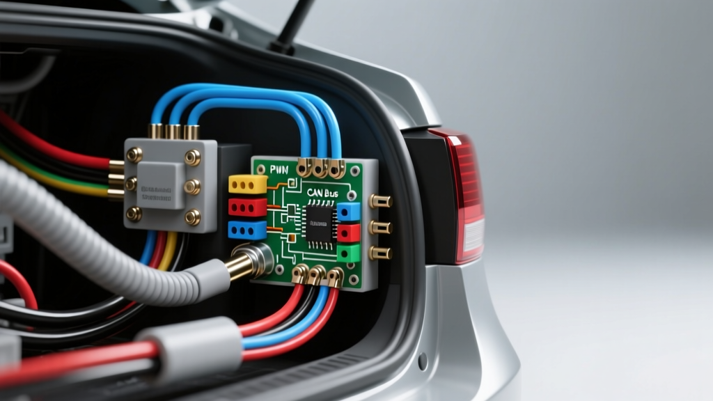
Decoding the Cost to Install an Aftermarket Backup Camera
When consumers research the cost to install an aftermarket backup camera, they are often met with flat, generalized estimates ranging from $150 to $300. However, as automotive electrical systems have evolved from simple analog circuits to complex multiplexed CAN bus networks, the actual labor and hardware requirements vary drastically. The true cost is dictated by the vehicle's specific wiring architecture, the necessity of Pulse Width Modulation (PWM) bypasses, and the routing complexity of 75-ohm composite video cables. This technical reference breaks down the electrical specifications, labor multipliers, and hardware requirements that dictate professional installation pricing.
Labor Time Multipliers: Wiring Complexity Tiers
Professional installers certified by the Mobile Electronics Certification Professional (MECP) program categorize backup camera installations into three distinct complexity tiers. These tiers determine the book time billed for labor, which typically ranges from $85 to $150 per hour depending on the region and shop overhead.
| Complexity Tier | Vehicle Architecture | Typical Labor Hours | Required Hardware & Modules | Estimated Labor Cost |
|---|---|---|---|---|
| Tier 1: Basic Analog | Pre-2012 vehicles, simple 12V reverse circuits | 1.5 - 2.5 Hours | RCA Cable, 18 AWG Wire, Posi-Taps | $125 - $250 |
| Tier 2: PWM / CAN Bus | 2015+ GM, Ford, Ram, BMW (Multiplexed lighting) | 3.0 - 4.5 Hours | CAN Bus Trigger (e.g., PAC TR-4), 12V Relay, RCA | $250 - $450 |
| Tier 3: OEM Integration | Factory head unit retention, FAKRA/Ethernet video | 5.0 - 8.0 Hours | Video Interface Module, FAKRA Adapters, Coding | $450 - $800+ |
The PWM Taillight Dilemma: Why Modern Installs Cost More
The single largest factor inflating the cost to install an aftermarket backup camera on modern vehicles is the transition from analog 12V reverse light circuits to Pulse Width Modulated (PWM) or LIN bus-controlled taillight assemblies. In vehicles like the 2019+ Ram 1500 or 2015+ BMW F-Series, the Body Control Module (BCM) does not send a steady 12V signal to the reverse bulbs. Instead, it sends a high-frequency PWM signal (often 60Hz to 400Hz) to monitor bulb integrity and manage power.
Failure Mode: Camera Flickering and Black Screens
CMOS backup cameras require a steady DC voltage (typically regulated internally from 12V down to 5V or 3.3V via a Low Dropout Regulator). If an installer taps directly into a PWM reverse wire, the camera receives rapid voltage pulses. This causes the camera's internal LDO to fail to maintain regulation, resulting in a flickering image, horizontal rolling bars, or a complete failure to initialize the video feed.
The Technical Fix: Relay Bypass or CAN Bus Trigger
To resolve this, technicians must install a PAC TR-4 Reverse Trigger Module or build a custom 12V relay bypass circuit. This adds to the hardware cost ($35-$65) and requires an additional 45 to 60 minutes of labor to route constant 12V and ground wires to the trigger module.
Standard 12V Relay Bypass Pinout (Bosch-Style 4-Pin/5-Pin):
- Pin 85 (Coil Ground): Tapped to a clean chassis ground using a ring terminal and self-tapping screw, or an existing M6 ground stud.
- Pin 86 (Coil Power): Tapped to the PWM reverse light wire. The relay coil draws minimal current (approx. 150mA) and will not trigger a BCM open-circuit fault code.
- Pin 30 (Common / Power In): Connected to a fused constant 12V source or an ignition-switched 12V source (e.g., radio accessory wire) using 16 AWG wire.
- Pin 87 (Normally Open / Power Out): Outputs a clean, steady 12V DC signal to the backup camera's power pigtail and the head unit's reverse trigger input.
Video Signal Routing and Ground Loop Prevention
Composite video signals operate at 1V peak-to-peak with a 75-ohm impedance. When routing the RCA video cable from the rear hatch or license plate area to the dashboard, installers must navigate through the vehicle's rubber weatherstripping looms and under the carpeting along the rocker panels.
The Ground Loop Phenomenon
A common issue that increases troubleshooting time (and therefore install cost) is the ground loop. This occurs when the camera's ground reference (usually tied to the taillight ground or rear chassis) and the aftermarket head unit's ground reference (tied to the dashboard chassis) have a slight voltage potential difference. This difference causes alternating current (AC) noise from the alternator to bleed into the video shield, manifesting as alternator whine in the audio system or severe visual interference on the camera feed.
Specification for Ground Isolation:
- Never ground the camera power wire to the taillight ground wire. Always run a dedicated 18 AWG ground wire to a verified, unpainted chassis bolt near the camera, or run the ground wire all the way back to the head unit's ground harness to establish a common star-ground topology.
- If a ground loop persists, an inline RCA Ground Loop Isolator (transformer-based, 10Hz to 100kHz frequency response) must be installed behind the head unit. This adds $15-$25 to the hardware cost and 15 minutes to the labor time.
Power and Ground Wiring Specifications
Adhering to standards set by the National Institute for Automotive Service Excellence (ASE) for electrical system modifications requires strict adherence to wire gauge and overcurrent protection specifications.
| Camera Power Draw | Cable Run Length | Recommended AWG | Max Voltage Drop Allowance |
|---|---|---|---|
| < 300mA (Standard CMOS) | Under 12 Feet (Sedans/Coupes) | 18 AWG | < 0.5V |
| < 300mA (Standard CMOS) | 12 to 20 Feet (SUVs/Trucks) | 16 AWG | < 0.5V |
| > 500mA (IR Night Vision/Heated) | Any Length | 16 AWG or 14 AWG | < 0.2V |
Using undersized wire (e.g., 20 AWG or 22 AWG often found in cheap Amazon camera kits) over long runs in vehicles like a Ford Transit or Chevy Express will result in a voltage drop that falls below the camera's minimum operating threshold, causing the infrared (IR) cut filter to click rapidly or the image to shut down entirely when the IR LEDs activate at night.
Connector Standards and Splicing Methodologies
The cheapest installations rely on 'scotch locks' or standard T-taps. These pierce the wire insulation, exposing the copper strands to moisture and galvanic corrosion, eventually leading to high-resistance connections and intermittent camera failure. A professional installation justifies its higher cost by utilizing proper splicing techniques:
- Posi-Taps: A threaded cap that compresses the main wire without severing the copper strands, while a secondary set screw bites into the tap wire. Ideal for tight harness spaces.
- Solder and Adhesive-Lined Heat Shrink: The gold standard for permanent, moisture-proof connections. Requires stripping the wire, twisting, soldering with rosin-core solder, and applying dual-wall heat shrink with a heat gun.
- Molex MX150 / Deutsch Connectors: For OEM-style tailgate handle cameras, technicians will depin the factory connector, add a new sealed pigtail, and re-pin the harness to avoid cutting factory wires entirely.
Summary: Justifying the Professional Install Cost
The cost to install an aftermarket backup camera is ultimately a reflection of the diagnostic time, wiring complexity, and hardware quality required to integrate a new video system into a modern vehicle's multiplexed electrical network. Bypassing PWM circuits, preventing ground loops, and utilizing aerospace-grade splicing methods ensure the camera operates reliably in all weather conditions without triggering BCM fault codes or draining the vehicle's battery.