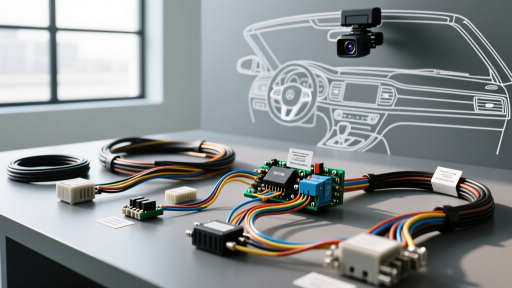
Introduction: The Hidden Dangers of Aftermarket Camera Integration
Upgrading or replacing the backup camera in modern vehicles is rarely a simple plug-and-play endeavor. When working on cars with reversing camera installed from the factory, or integrating aftermarket systems into late-model CAN-bus networks, installers frequently encounter complex electrical architectures. A simple miswire can result in flickering video feeds, drained batteries, or catastrophic damage to the head unit's internal PCB. This guide details the five most common and destructive wiring mistakes made during reverse camera installation, providing exact technical corrections, AWG specifications, and safety warnings to ensure a reliable, noise-free video signal.
Mistake 1: Tapping Directly into PWM Reverse Light Circuits
The Hazard: Camera Flickering and CAN-Bus Faults
In vehicles manufactured after 2014 (particularly FCA/Stellantis, BMW, Volkswagen, and Ford models), the reverse light circuit is rarely a solid 12V DC feed. Instead, the Body Control Module (BCM) uses Pulse Width Modulation (PWM) to monitor bulb health and dim the lights. If you use a standard T-tap to pull 12V power and the RCA trigger signal directly from a PWM reverse wire, the camera will receive a pulsing square wave rather than a steady DC voltage.
The Technical Reality
A standard digital multimeter might read 10.5V to 11.8V on a PWM circuit, tricking installers into thinking it is a clean 12V source. However, an oscilloscope will reveal a 12V square wave pulsing at varying frequencies. CMOS camera sensors require a clean, ripple-free 12V DC supply. Feeding them PWM voltage causes the camera's internal voltage regulator to overheat, resulting in a flickering image, rolling horizontal bars, or complete camera failure. Furthermore, drawing extra current can trigger a BCM open-circuit fault, throwing a "Reverse Light Malfunction" code on the dash.
The Correct Fix
Never tap a PWM wire directly. You must install a 12V DC smoothing filter relay or a dedicated CAN-bus reverse light adapter (e.g., PAC TR-4 or OEM-specific Fakra Z to RCA bypass modules). If building a custom filter, use a 1N4007 diode to block reverse voltage spikes and a 1000µF 25V electrolytic capacitor to smooth the PWM signal into a steady 12V DC output before feeding the camera's red power wire and the RCA trigger shield.
Mistake 2: Improper Grounding and Ground Loop Induction
The Hazard: Alternator Whine and Static Interference
One of the most frequent complaints after installing a reverse camera in cars with reversing camera installed previously is a high-pitched alternator whine or static bars that fluctuate with engine RPM. This is almost always caused by a ground loop.
The Technical Reality
A ground loop occurs when the camera's ground (usually at the trunk latch) and the head unit's ground (at the dashboard) are at different electrical potentials. The RCA cable's outer shield acts as the ground reference for the video signal. If the trunk ground has a resistance of 2.5 ohms (due to being bolted to painted sheet metal) and the dash ground is 0.2 ohms, the 2.3-ohm differential forces parasitic current to flow through the RCA shield. This current modulates with the alternator's AC ripple, injecting noise directly into the video signal.
The Correct Fix
Abandon the factory tail-light ground wire for the camera. Run a dedicated 14 AWG GXL ground wire from the camera's black pigtail directly to a verified, bare-metal chassis point in the trunk. Sand away any paint or rust, use a stamped copper ring terminal (not a cheap crimp fork), and secure it with an M6 or M8 zinc-plated bolt. Verify the ground with a multimeter; the resistance between the camera ground and the vehicle's negative battery terminal must read under 0.5 ohms.
Mistake 3: Overloading the Head Unit's Reverse Trigger Wire
The Hazard: Fried Head Unit PCB Traces
Aftermarket head units (Pioneer, Kenwood, Alpine) feature a reverse trigger wire (typically Purple/White or Orange/White) designed to tell the radio to switch to the camera input. Many installers mistakenly wire the camera's main 12V+ power wire and the RCA trigger wire directly to this head unit wire.
The Technical Reality
The head unit's reverse trigger output is a low-current logic signal. According to most manufacturer schematics, this trace is rated for a maximum of 300mA. A standard CMOS reverse camera draws between 400mA and 800mA upon startup due to the inrush current of its IR LEDs and internal processor. Tying the camera's main power to the head unit trigger will instantly overload the trace, melting the internal PCB pathway and permanently disabling the radio's reverse-switching capability.
The Correct Fix
Isolate the circuit using a standard Bosch ISO 7588 5-pin automotive relay.
- Pin 86: Connect to the Head Unit Purple/White reverse trigger wire (18 AWG).
- Pin 85: Connect to a clean chassis ground (16 AWG).
- Pin 30: Connect to a fused 12V constant or ignition source via a 15A ATO fuse (14 AWG).
- Pin 87: Connect to the Camera's Red 12V+ wire and the RCA trigger wire (16 AWG).
Mistake 4: EMI Routing Violations Alongside High-Current Power
The Hazard: Severe Video Degradation and Signal Dropout
Routing the RCA video cable down the same door sill kick-plate loom as the 4 AWG or 8 AWG power wire for an aftermarket amplifier is a critical violation of electromagnetic compatibility.
The Technical Reality
High-current power wires generate a significant electromagnetic field (EMF). The RCA cable carries a low-voltage (typically 1V peak-to-peak) analog composite video signal. When routed parallel to high-current DC wires, the RCA acts as an antenna, inductively coupling the EMF noise into the video feed. This manifests as snow, color distortion, or complete signal dropout when the audio system is playing at high volume or when power windows are actuated.
The Correct Fix
Follow SAE J1113 Electromagnetic Compatibility Standards for wire routing. Always route the RCA video cable and the reverse trigger wire down the driver's side of the vehicle, and route all high-current amplifier power wires down the passenger's side. If they must cross, ensure they intersect at a strict 90-degree angle to minimize inductive coupling.
Mistake 5: Trunk Hinge Grommet Weatherproofing Failures
The Hazard: Water Ingress and CAN-Bus Short Circuits
Passing wires from the trunk lid into the main cabin requires navigating the rubber trunk hinge grommet. Using standard vinyl electrical tape to bundle wires here guarantees failure.
The Technical Reality
The trunk hinge area experiences extreme temperature fluctuations and constant mechanical flexing. Vinyl tape adhesive turns to a gummy residue in the summer heat and cracks in the winter cold. Once the tape fails, water wicks down the wire loom via capillary action directly into the BCM or the camera's PCB, causing severe CAN-bus short circuits and corrosion.
The Correct Fix
Use adhesive-lined marine-grade heat shrink tubing (with a 3:1 shrink ratio) on all solder joints near the camera pigtail. Wrap the entire wire loom passing through the grommet in Tesa 51036 PET cloth tape (the OEM standard for automotive harnesses) to provide abrasion resistance against the rubber grommet, and apply a dab of dielectric silicone grease where the wires enter the camera housing.
Reverse Camera Wiring Specification & Safety Chart
| Circuit Application | Recommended AWG | Wire Type | Connection Method | Safety / Fusing Requirement |
|---|---|---|---|---|
| Camera Main 12V+ Power | 16 AWG | GXL / TXL | Solder & Adhesive Heat Shrink | 5A or 10A Mini ATO Fuse (within 18" of source) |
| Camera Chassis Ground | 14 AWG | GXL / TXL | Ring Terminal to Bare Metal (M6/M8) | None (Must be < 0.5 Ohms resistance) |
| Head Unit Logic Trigger | 18 AWG | Stranded Copper | Posi-Tap or Solder | Max 300mA Draw (Use Relay for higher) |
| RCA Video Shield Ground | N/A (Coax) | RG59 / Shielded Coax | RCA Plug / Fakra Z Adapter | Must share common ground plane with HU |
Video Signal Failure Troubleshooting Decision Tree
Use this diagnostic tree to identify the root cause of camera failures in cars with reversing camera installed systems:
- Symptom: Camera image flickers rapidly or rolls vertically.
- Cause: PWM voltage on the reverse light tap.
- Fix: Install a 12V DC smoothing filter relay between the reverse light and camera power.
- Symptom: High-pitched whine that changes pitch with engine RPM.
- Cause: Ground loop due to high-resistance trunk ground.
- Fix: Run a dedicated 14 AWG ground to a sanded, bare-metal chassis point.
- Symptom: Head unit switches to camera input, but screen is black/blue.
- Cause: Blown head unit internal trace from trigger overload.
- Fix: Bypass internal trace by wiring the reverse trigger signal directly to the RCA video switch box or use a relay isolation harness.
- Symptom: Heavy static or 'snow' only when the radio volume is high.
- Cause: Electromagnetic Interference (EMI) from amplifier power wires.
- Fix: Reroute RCA video cable down the opposite side of the vehicle from the amplifier power wire.
Authoritative References & Further Reading
To ensure your installations meet automotive safety and electrical standards, consult the following resources:
- SAE J1113 Electromagnetic Compatibility Standards - Essential guidelines for routing low-voltage signal wires away from high-current EMI sources in automotive environments.
- Haynes Automotive Wiring Basics - Comprehensive reference for proper crimping, soldering, and AWG load-capacity charts for 12V DC mobile electronics.
- SEMA Technology Committee: Understanding CAN-Bus Systems - Critical reading for installers working on late-model vehicles to avoid triggering BCM faults when tapping reverse lighting circuits.