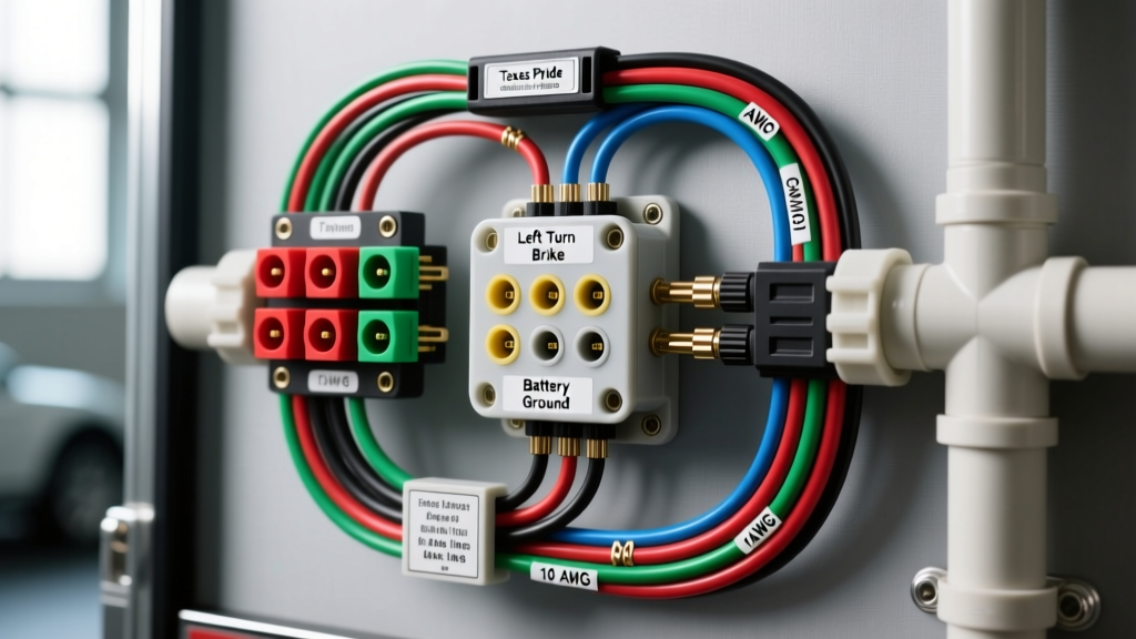
Introduction to Texas Pride Electrical Architecture
Texas Pride Trailers are engineered for heavy-duty utility, car hauling, and equipment transport. Built with robust steel frames, diamond plate decking, and heavy-gauge crossmembers, these trailers demand an equally robust electrical architecture. When referencing a Texas Pride trailer wiring diagram, it is critical to understand that the factory harness is designed around the SAE J286 standard for 7-way RV blade connectors. However, the sheer length of Texas Pride car haulers (often 16 to 24 feet) and the high amperage draw of dual or triple electric brake axles introduce complex voltage drop and grounding challenges that standard passenger vehicle wiring guides fail to address.
This advanced technical deep dive dissects the 7-pin wiring schematic, focusing on AWG wire sizing, breakaway switch integration, electric brake circuit dynamics, and advanced troubleshooting for ground faults inherent to heavy steel trailer chassis.
The Standard 7-Way RV Blade Pinout (SAE J286)
The 7-way flat blade connector is the industry standard for trailers equipped with electric brakes and auxiliary power requirements. Below is the definitive pinout chart for a Texas Pride 7-pin harness, including the required wire gauges and circuit protection specifications to prevent harness meltdowns under heavy load.
| Pin Position | Function | Standard Wire Color | Minimum AWG | Circuit Protection / Notes |
|---|---|---|---|---|
| Pin 1 (Top) | Ground Return | White | 10 AWG (or 8 AWG) | Must bond directly to tow vehicle chassis. Do not rely on the hitch ball. |
| Pin 2 | Electric Brakes | Blue | 10 AWG | 30A Auto-Reset Breaker. Carries up to 12-15A per axle under heavy braking. |
| Pin 3 | Tail / Running Lights | Brown | 12 AWG | 15A Fuse. Powers all clearance, marker, and tail lights. |
| Pin 4 | Right Turn / Stop | Green | 12 AWG | 20A Fuse. Combined stop/turn circuit. |
| Pin 5 | Left Turn / Stop | Yellow | 12 AWG | 20A Fuse. Combined stop/turn circuit. |
| Pin 6 | 12V Auxiliary Power | Black or Red | 10 AWG | 40A Breaker. Charges breakaway battery or powers interior cargo lights. |
| Pin 7 (Center) | Reverse Lights / Aux | Purple | 14 AWG | 15A Fuse. Often used to trigger reverse lockout solenoids on surge brakes. |
Reference: Pin configurations align with the SAE J286 Standard for commercial and recreational vehicle connectors.
Deep Dive: Electric Brake Circuit & Voltage Drop
The most common failure mode on long Texas Pride equipment trailers is weak braking performance caused by voltage drop across the blue brake wire. Electric brake magnets typically require 12.0V to 13.5V at the hub to generate maximum clamping force (often rated at 3,500 to 7,000 lbs per axle).
When a tow vehicle's brake controller outputs 12V, the current must travel through the truck's wiring, the 7-pin connector, and the entire length of the trailer frame to reach the rear axles. On a 22-foot Texas Pride car hauler, a standard 12 AWG blue wire will experience significant resistance. According to Ohm's Law and standard copper resistance tables, a 20-foot run (40 feet round-trip) of 12 AWG wire carrying 12 Amps will drop approximately 3.8 Volts. This leaves only 8.2 Volts at the brake magnets, resulting in a 40% loss of braking power.
The Engineering Fix
- Upgrade to 10 AWG: Always use a minimum of 10 AWG stranded copper wire for the blue brake circuit on trailers exceeding 14 feet in length.
- Parallel Grounding: Run a dedicated 10 AWG white ground wire alongside the blue brake wire directly to each brake backing plate, rather than relying on the steel trailer frame to complete the circuit to the front 7-pin plug.
- Brake Controller Calibration: After upgrading wire gauge, recalibrate your proportional brake controller (e.g., Tekonsha Prodigy P3 or CURT Spectrum). The increased voltage at the magnets will require a lower gain setting to prevent wheel lockup.
Breakaway Switch Integration & Battery Wiring
Texas Pride trailers equipped with electric brakes are legally required to have a functional breakaway system. This system is designed to apply full trailer braking power if the trailer separates from the tow vehicle. Understanding the wiring logic of this circuit is vital for safety and DOT compliance.
The breakaway switch is a Normally Closed (NC) mechanical switch held open by a nylon pin and lanyard. When the lanyard pulls the pin, the switch closes, completing a circuit between the onboard 12V breakaway battery and the blue electric brake wire.
Critical Wiring Rules for Breakaway Systems
- Independent Power Source: The breakaway switch must draw power from a dedicated onboard 12V battery (usually a 5Ah to 12Ah SLA battery mounted in a weatherproof box on the trailer tongue). It must never be wired directly to the tow vehicle's 12V auxiliary pin (Pin 6). If the trailer detaches, the 7-pin connection is severed, rendering a tow-vehicle-powered breakaway system completely useless.
- Pin 6 Charging Circuit: Pin 6 (Black/Red) from the 7-way plug should be routed through a 40A auto-reset breaker to a battery isolator or a smart charge relay, which then maintains the breakaway battery while driving without allowing the trailer to drain the tow vehicle's battery when parked.
- Splice Placement: The breakaway switch output wire must splice into the blue brake wire after the main harness split, ensuring power reaches all axles simultaneously. Use marine-grade heat-shrink butt connectors with adhesive lining to prevent moisture intrusion at the splice joint.
Advanced Troubleshooting: Grounding & Multiplexed Systems
If you are diagnosing a Texas Pride trailer wiring diagram issue where lights dim when brakes are applied, or turn signals back-feed into the running lights, you are experiencing a classic ground fault. Heavy steel trailers are highly susceptible to chassis grounding failures due to powder coating, rust, and flexing at the hitch joint.
The 'White Wire' Star-Washer Protocol
Never use self-tapping screws with painted ring terminals to ground trailer lights to the chassis. The proper methodology for terminating ground wires on a Texas Pride steel frame involves:
- Drilling a clean hole through the frame or crossmember.
- Removing all paint, powder coat, and rust down to bare, shiny metal using a flap disc or sandpaper.
- Applying a star washer (internal tooth lock washer) between the bare metal and the ring terminal to bite through any micro-corrosion.
- Securing with a Grade 8 bolt and nyloc nut.
- Coating the entire termination point in dielectric grease or fluid film to halt future oxidation.
For multiplexed tow vehicles (common in modern Ford F-Series, Ram HD, and GM Silverado trucks utilizing PWM lighting modules), a poor ground will cause the truck's Body Control Module (BCM) to detect an out-of-range resistance fault, triggering a 'Trailer Wiring Fault' dash warning and cutting power to the trailer plug. Upgrading the main ground wire (Pin 1) to 8 AWG and bonding it directly to the truck's frame and the trailer's main tongue crossmember usually resolves BCM communication errors.
LED Lighting Upgrades & Hyperflash Mitigation
Many owners upgrade their Texas Pride trailers from standard 1157 incandescent bulbs to sealed LED trailer lights. While LEDs draw a fraction of the amperage (typically 0.2A per fixture vs. 2.1A for incandescent), this low draw can confuse older or highly sensitive tow vehicle flasher relays, resulting in 'hyperflash' (rapid blinking).
If your truck's BCM requires a minimum load to register the trailer circuit, you must install load resistors (typically 6 Ohm, 50W) in parallel with the left (yellow) and right (green) turn signal circuits. Mount these resistors to the bare steel trailer frame, as they generate significant heat during operation and can melt plastic wire looms if improperly secured. Alternatively, installing an LED-specific smart flasher relay in the tow vehicle bypasses the need for resistors entirely.
Authoritative References & Further Reading
For ongoing maintenance and electrical schematics, always consult the manufacturer's specific documentation and industry standards:
- SAE International - J286 Standard for Trailer Connectors
- RV Industry Association (RVIA) Low Voltage Wiring Guidelines
- CURT Manufacturing - 7-Way RV Blade Technical Bulletins
By adhering to these advanced wiring protocols, you ensure that your Texas Pride trailer's electrical system remains safe, DOT-compliant, and resilient against the harshest towing environments.