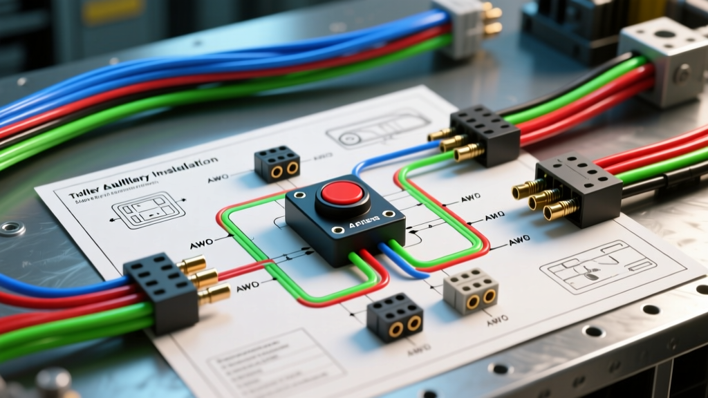
Mastering the 4 Pin Push Button Switch Wiring Diagram for Trailer Auxiliaries
When outfitting a tow vehicle or heavy-duty truck to control trailer-mounted auxiliaries—such as electric winches, hydraulic dump beds, or high-draw LED light bars—the cabin interface is just as critical as the load itself. The standard 4 pin push button switch is the industry default for these 12V DC applications. However, misunderstanding the internal terminal layout or bypassing a relay for high-amperage loads is a leading cause of melted dash panels, voltage drops, and electrical fires.
This practical how-to guide breaks down the exact 4 pin push button switch wiring diagram, terminal pinouts, AWG sizing requirements, and relay integration necessary for a safe, SAE-compliant installation. Whether you are wiring a momentary switch for a trailer winch or a latching switch for auxiliary work lights, the principles of high-current DC switching remain the same.
Understanding the 4-Pin Terminal Layout
Before cutting any wire, you must understand the anatomy of the switch. A standard automotive 4-pin push button switch is typically a Single Pole, Single Throw (SPST) configuration with an integrated LED indicator. It features four distinct terminals, usually color-coded or marked on the switch housing.
| Pin Number | Terminal Color | Function | Connection Destination |
|---|---|---|---|
| Pin 1 | Silver / Brass | 12V Power In | Fused Ignition or Accessory Source |
| Pin 2 | Silver / Brass | 12V Load Out | Relay Pin 86 (Coil Positive) |
| Pin 3 | Gold / Copper | LED Positive | Jumper to Pin 1 or Separate Switched 12V |
| Pin 4 | Gold / Copper | LED Negative | Chassis Ground or Relay Pin 85 |
Expert Note: The LED pins (3 and 4) are polarity-sensitive. If you connect them backward, the switch will still pass current to your relay, but the internal LED will not illuminate. Furthermore, many cheap import switches do not feature reverse-polarity protection diodes, meaning reversed LED pins can short out and blow your cabin fuse.
Momentary vs. Maintained: Choosing the Right Action
When sourcing your switch for trailer applications, you must select the correct mechanical action:
- Momentary (Normally Open): The circuit is only complete while you physically hold the button down. This is mandatory for trailer winches, hydraulic lift gates, and dump beds. If a control wire snags or the switch jams, a momentary switch prevents the motor from running unattended and burning out.
- Maintained (Latching): The button clicks and stays engaged until pressed again. Use this only for trailer auxiliary lighting, onboard air compressors, or 12V cooler circuits where continuous operation is desired without constant physical pressure.
The Golden Rule: Never Switch High-Amp Loads Directly
The most catastrophic mistake DIYers make with a 4 pin push button switch wiring diagram is attempting to run the trailer load directly through the dashboard switch. A standard dash switch is rated for 15 to 20 amps maximum. A trailer winch can easily pull 100+ amps under stall load, and a hydraulic pump motor can draw 40 amps on startup.
Passing 40 amps through a 20-amp dash switch will cause the internal contacts to arc, weld together, and eventually melt the plastic housing, potentially igniting a dash fire. You must use the switch solely to trigger a heavy-duty ISO Mini Relay or a continuous-duty solenoid.
According to the Littelfuse Automotive Relay Guide, a standard 4-pin ISO mini relay (Bosch style) safely handles up to 40 amps on the switching contacts (Pins 30 and 87), while the coil (Pins 85 and 86) draws less than 150 milliamps. This allows your delicate 4-pin dash switch to control massive trailer loads safely.
Step-by-Step Installation & Wire Sizing
For the control circuit (dash to relay), we adhere to SAE J1128 standards for low-tension primary cable. For under-hood routing to the trailer connector, always use Cross-Linked (GXL or TXL) wire rather than standard PVC, as it withstands higher engine bay temperatures and resists abrasion.
Step 1: Power Feed and Fusing
Run a 14 AWG red wire from a switched 12V source (like your tow package brake controller feed or an auxiliary fuse block). Install an inline 10A blade fuse within 6 inches of the power source. This protects the wire running into your cabin in the event of a short circuit.
Step 2: Wiring the Switch Terminals
- Pin 1: Connect the fused 12V power feed.
- Pin 2: Connect a 14 AWG wire (typically Blue or Yellow) and route it through the firewall to the engine bay relay block.
- Pin 3: Jumper this to Pin 1 if you want the LED to illuminate only when the key is on and the switch is powered. Alternatively, run to a dedicated dash illumination circuit if you want the LED to dim with your headlights.
- Pin 4: Connect to a clean, bare-metal chassis ground using a ring terminal.
Step 3: Integrating the ISO Relay
Mount a 4-pin or 5-pin ISO relay in a weatherproof fuse/relay box under the hood.
- Pin 86: Connect the Blue/Yellow wire from Switch Pin 2.
- Pin 85: Connect to a solid chassis ground (14 AWG Black wire).
- Pin 30: Connect to the vehicle battery positive via a 40A or 50A Maxi-Fuse. Use 10 AWG or 8 AWG wire depending on the trailer load.
- Pin 87: Connect to the trailer auxiliary feed wire (10 AWG). Note: If using a 5-pin relay, tape off and isolate Pin 87a (Normally Closed) so it does not ground out.
Trailer-Side Integration: 7-Way vs. Anderson Powerpole
How you transfer this switched power to the trailer depends on your amperage requirements.
For Low-Draw Auxiliaries (Under 15A):
You can route the output from Relay Pin 87 directly to Pin 4 (12V Aux) on your vehicle's 7-Way RV blade connector. Ensure the trailer side wiring is protected with Aptiv Weather-Pack sealed connectors to prevent green corrosion from road spray and winter salt.
For High-Draw Auxiliaries (Winches, Dump Beds - 30A+):
Do not push 40 amps through a standard 7-Way RV plug; the brass pins will overheat and melt the plastic housing. Instead, install a 50A Anderson SB50 connector or a dedicated heavy-duty solenoid at the rear bumper. Run 8 AWG wire directly from the battery to the Anderson plug, using the 4-pin switch and relay only to trigger the solenoid's ground or positive coil.
Troubleshooting Common Switch & Relay Failures
Even with a perfect 4 pin push button switch wiring diagram, real-world trailer environments introduce vibration, moisture, and voltage drop. Use this diagnostic tree when issues arise:
- Symptom: Switch LED illuminates, but relay does not click.
Cause: Open circuit on the coil ground (Pin 85) or high resistance on the switch output wire (Pin 2). Fix: Perform a voltage drop test across the switch. A healthy switch should drop less than 0.1V when depressed. - Symptom: Relay clicks loudly, but trailer winch/lights do not engage.
Cause: Pitted contacts inside the relay on Pins 30 and 87, or a blown main Maxi-Fuse. Fix: Bypass the relay temporarily with a heavy-gauge jumper wire. If the load runs, replace the relay. Internal arcing frequently destroys ISO relays used for inductive loads like winch motors. - Symptom: Switch housing feels warm or hot to the touch.
Cause: The installer bypassed the relay and is routing the trailer load directly through the dash switch. Fix: Disconnect immediately. The internal copper wiper is overheating and poses a severe fire risk. Rewire using the relay schematic above. - Symptom: LED flickers or dims when trailer load engages.
Cause: Severe voltage drop on the main power feed, or the switch LED ground (Pin 4) is sharing a dirty ground with the trailer load. Fix: Run a dedicated 14 AWG ground wire for the switch LED back to the cabin grounding bus bar.
Final Best Practices for Crimping and Sealing
Never use solder-only connections for trailer wiring. The constant harmonic vibration from towing will cause solder joints to fatigue and snap. Always use a ratcheting crimper with adhesive-lined heat shrink terminals. The adhesive lining melts during the shrinking process, creating a waterproof seal that blocks capillary action from drawing moisture up into the copper strands. Finally, pack all exposed trailer-side connectors with dielectric grease to ensure your auxiliary circuits function flawlessly in rain, mud, and snow.