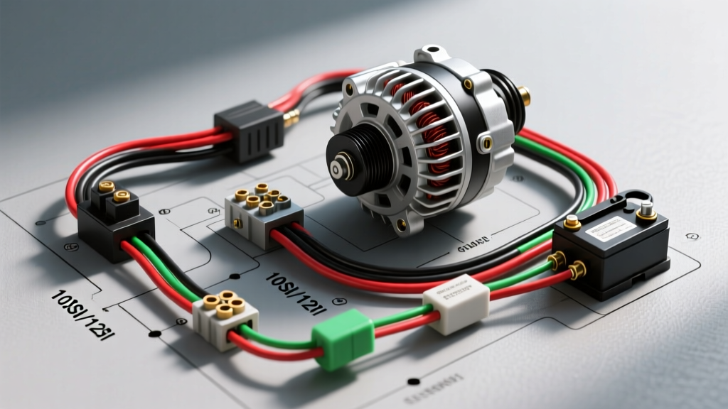
The Delco 10SI and 12SI Legacy on the 350 SBC
When rebuilding, swapping, or upgrading a classic Chevy 350 Small Block (SBC), the charging system is often the last hurdle in getting the engine to run reliably. The ubiquitous Delco 10SI and 12SI alternators are the gold standard for classic GM V8 applications. However, finding a reliable 350 Chevy alternator wiring diagram that explains the difference between the factory 3-wire harness and the popular aftermarket 1-wire conversion can be frustrating. Many builders struggle with undercharging at idle, burnt-out dash bulbs, or melted main output wires due to improper gauge sizing and poor terminal crimping.
This practical how-to installation guide breaks down the exact pinouts, wire color codes, and AWG specifications required to wire a GM 10SI or 12SI alternator to a 350 Chevy. Whether you are restoring a 1970s C10 truck with a factory gauge cluster or building a carbureted street rod that demands a simplified 1-wire setup, this guide provides the actionable, expert-level electrical data you need to do the job right the first time.
Decoding the 350 Chevy Alternator Wiring Diagram
The classic GM 10SI and 12SI alternators utilize an internal voltage regulator and a distinctive rectangular 2-pin connector (Packard 56 series). To properly wire the alternator, you must understand the function of the three primary electrical connection points on the unit: the BAT terminal, Terminal #1, and Terminal #2.
The Main Output (BAT Terminal)
The threaded stud on the back of the alternator is the main battery output. This is where the rectified DC voltage exits the alternator and travels to the battery and main fuse block. The most common failure point in a 350 Chevy charging system is using undersized wire for this connection, leading to voltage drop and melted insulation.
Terminal #1 (Exciter / Lamp Circuit)
Terminal #1 serves two critical functions. First, it acts as the 'exciter' circuit, providing the initial 12V surge required to 'turn on' the alternator's internal rotor field. Second, it grounds through the dashboard 'ALT' or 'GEN' idiot light. If the bulb burns out or is removed in a custom dash setup, the alternator will not excite, and the vehicle will run solely on battery power until it dies.
Terminal #2 (Voltage Sense Circuit)
Terminal #2 is the voltage sense wire. The internal regulator uses this wire to read the actual voltage at the battery or main bus bar. If this wire is missing, damaged, or simply jumpered to the BAT terminal at the back of the alternator, the regulator only senses voltage at the alternator itself. This causes the system to undercharge the battery because it does not account for the voltage drop across the main output wire and firewall connections.
Terminal Pinout and Specification Chart
| Terminal / Post | Function | Standard Wire Color | Recommended AWG Size | Connector Type |
|---|---|---|---|---|
| BAT (Main Stud) | Main DC Output to Battery | Red | 8 AWG (up to 90A) / 4 AWG (100A+) | 1/4' Ring Terminal |
| Terminal #1 (L) | Exciter / Dash Lamp Feed | White or Red/White | 16 AWG to 18 AWG | Packard 56 Female Spade |
| Terminal #2 (S) | Battery Voltage Sense | Red | 14 AWG to 16 AWG | Packard 56 Female Spade |
Step-by-Step 3-Wire Installation Guide
The 3-wire setup is the most efficient and reliable way to wire a 350 Chevy alternator, ensuring optimal battery life and stable voltage for aftermarket accessories like electric cooling fans and MSD ignition boxes.
Step 1: Preparing the Main Output Wire
Measure the distance from the alternator BAT terminal to the main battery positive post or the starter solenoid main lug (if using a fusible link). Cut a length of 8 AWG (for standard 60-90A units) or 4 AWG (for 100A+ high-output units) stranded copper wire. Strip 1/2 inch of insulation and crimp a heavy-duty, closed-barrel 1/4' ring terminal using a hex-crimp tool. Slide adhesive-lined marine heat shrink over the joint and apply heat until the sealant extrudes slightly. Secure the wire to the BAT terminal and torque the nut to 65 in-lbs. Over-torquing will strip the delicate threads on the alternator output stud.
Step 2: Wiring the Exciter Circuit (Terminal #1)
Using 16 AWG wire, connect Terminal #1 to the 'IGN' switched side of your dash indicator light. If your custom 350 build does not use a dash indicator light, you must install a 10-ohm, 2-watt resistor in parallel with the wire leading to a switched 12V ignition source. This resistor provides the necessary initial resistance to excite the rotor field without drawing excessive current. Without this resistor or a functional dash bulb, the alternator will fail to charge upon startup.
Step 3: Routing the Voltage Sense Wire (Terminal #2)
Run a 14 AWG red wire from Terminal #2 directly to the positive terminal of the battery or the main input lug of your under-hood fuse block. This 'remote voltage sensing' ensures the internal regulator compensates for any voltage drop in the main charging cable. As noted by the electrical experts at M.A.D. Enterprises, remote sensing is the single most effective way to cure dimming headlights and slow-cranking issues in classic Chevy trucks.
The 1-Wire Conversion: Myth vs. Reality
Many aftermarket companies sell '1-wire' alternators for the 350 Chevy. These are simply standard 10SI or 12SI units that have been internally modified. The modification involves a jumper wire connecting the BAT terminal directly to Terminal #1 and Terminal #2 internally or via a small external pigtail.
How it works: When you start the engine, the alternator does not immediately begin charging. You must 'rev' the 350 Chevy past 1,500 RPM to generate enough residual magnetism in the rotor to trigger the internal self-excite circuit. Once triggered, it begins charging.
The Drawbacks: While a 1-wire setup cleans up the engine bay, it suffers from two major flaws. First, the voltage is sensed directly at the back of the alternator, not at the battery, leading to chronic undercharging of the battery. Second, if the vehicle sits for a few weeks and the battery drains slightly, the residual magnetism may be too weak to self-excite, leaving you stranded. For a reliable daily driver or tow rig, the 3-wire diagram is vastly superior. For a trailer queen or show car, the 1-wire is acceptable.
Upgrading to the CS130 / CS144 for High-Amp Applications
If your 350 Chevy is equipped with dual high-draw electric cooling fans, an electric fuel pump, and a modern EFI system, the 10SI (max 90A) will not suffice. You must upgrade to a GM CS130 or CS144 alternator, which can produce 130A to 140A.
The CS-series uses a 4-pin oval connector, but only three pins are typically used in retrofit applications:
- Pin L (Lamp): Connects to the ignition switch via a 470-ohm resistor or a standard 194 LED bulb.
- Pin S (Sense): Connects directly to the battery positive.
- Pin F (Field): Usually left unconnected unless driven by an external PCM-controlled regulator.
When installing a CS144 on a classic 350 block, you will need an adapter bracket kit, as the CS mounting ears are slightly wider than the 10SI. Always use Grade 8 hardware for the mounting bolts and torque them to 30-35 ft-lbs to prevent case cracking and misalignment of the pulley grooves.
Troubleshooting Common 350 Chevy Charging Issues
Even with a perfect wiring diagram, real-world garage conditions can introduce faults. Use this decision tree to diagnose your 350 Chevy charging system:
- Symptom: Alternator whines and voltage spikes above 15.5V.
Cause: The voltage sense wire (Terminal #2) is broken, disconnected, or has high resistance. The regulator thinks the battery is dead and is full-fielding the alternator.
Fix: Check continuity from Terminal #2 to the battery positive post. Repair or replace the sense wire. - Symptom: Dash ALT light stays on after engine starts.
Cause: A short to ground on the Terminal #1 exciter wire, or a failed internal diode trio.
Fix: Disconnect the 2-pin plug. If the light goes out, the alternator is internally shorted and requires a rebuild. If the light stays on, trace the wiring harness for a chafed wire touching the exhaust manifold or block. - Symptom: Battery dies overnight, but charges fine while running.
Cause: Parasitic draw caused by a shorted rectifier diode inside the alternator, allowing AC ripple and battery current to flow backward through the stator.
Fix: Perform a parasitic draw test with a multimeter. If the draw drops significantly when the main BAT wire is removed from the alternator, replace the alternator or install an inline battery disconnect switch.
Final Wiring and Routing Best Practices
When routing your alternator wires on a 350 SBC, keep the main output cable as far away from the exhaust manifolds and headers as physically possible. Chevy 350 headers radiate immense heat, and standard PVC wire insulation will melt and short against the block at 105°C. Use Tefzel (TXL) cross-linked wire for all under-hood alternator routing, as it withstands temperatures up to 150°C and features a thinner insulation wall, making it easier to route through tight firewall grommets.
For comprehensive harness routing techniques and fuse sizing calculations for high-output GM charging systems, refer to the technical wire guides provided by Painless Performance Products. Properly fusing the main output wire with a Class-T fuse or a Mega Fuse (rated at 125% of the alternator's maximum output) is mandatory to prevent catastrophic electrical fires in the event of a short circuit or front-end collision.