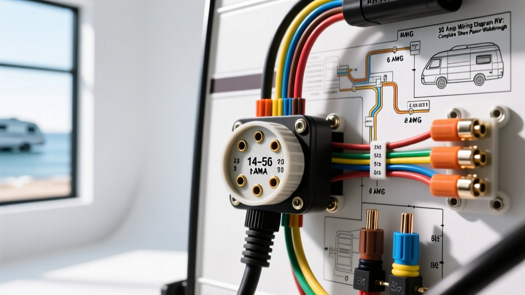
Introduction to 50-Amp RV Shore Power Systems
When upgrading or troubleshooting a modern recreational vehicle, understanding the 50 amp wiring diagram RV configuration is critical for safety and functionality. Unlike the standard 30-amp TT-30 system which provides a single 120V leg, a 50-amp RV service utilizes a 120/240V split-phase system. This allows high-draw appliances—such as dual roof air conditioners, residential refrigerators, and induction cooktops—to operate simultaneously without tripping the main pedestal breaker.
This complete walkthrough dissects the journey of AC power from the campground pedestal, through the NEMA 14-50 shore cord, into the Automatic Transfer Switch (ATS), and finally to the RV’s main distribution panel. We will cover exact wire color codes, AWG sizing, torque specifications, and common failure modes that lead to catastrophic electrical fires.
The NEMA 14-50 Receptacle and Plug Pinout Diagram
The 50-amp RV shore power cord terminates in a NEMA 14-50P plug, which mates with a NEMA 14-50R receptacle at the park pedestal. This is a 4-prong, 3-pole, 4-wire grounding configuration rated for 125/250V. Misidentifying these pins is the leading cause of fried RV electronics.
| Pin Designation | Function | Standard Wire Color | Voltage Potential |
|---|---|---|---|
| Pin X (Right Hot) | Line 1 (L1) | Black | 120V to Neutral / 240V to L2 |
| Pin Y (Left Hot) | Line 2 (L2) | Red | 120V to Neutral / 240V to L1 |
| Pin W (Bottom Neutral) | Neutral (N) | White | 0V (Current Carrier) |
| Pin G (Top Ground) | Equipment Ground | Green | 0V (Safety Path) |
Complete Wiring Walkthrough: Shore Cord to Main Panel
Step 1: The Shore Power Inlet and Junction Box
The NEMA 14-50P plugs into the RV’s exterior shore power inlet (often a Marinco or Hubbell 50A inlet). From the inlet, a heavy-duty 6 AWG SOOW (Service, Oil-resistant, Oil-resistant, Water-resistant) flexible cord routes through the RV’s underbelly to the main junction box or directly to the Automatic Transfer Switch. The SOOW jacket is rated for 600V and resists abrasion, chemicals, and moisture—critical for the harsh undercarriage environment.
Expert Tip: Always apply a dielectric grease (like NO-OX-ID A-Special) to the inlet pins to prevent galvanic corrosion, which increases resistance and causes the inlet to melt under sustained 40+ amp loads.
Step 2: Automatic Transfer Switch (ATS) Integration
Most 50-amp RVs are equipped with an onboard generator (typically 5,500W to 12,500W). The ATS ensures that shore power and generator power never backfeed into each other. In a 50-amp diagram, the ATS must be a 3-pole contactor type, switching Line 1, Line 2, and the Neutral simultaneously.
- Shore Power Neutral: Bonded to ground at the campground pedestal transformer.
- Generator Neutral: Bonded to ground internally at the generator chassis.
If the ATS only switches the two hot legs and leaves the neutral tied together, you create a parallel neutral-to-ground path when on generator power, which can trip GFCI breakers and cause stray voltage on the RV chassis. Refer to the Recreation Vehicle Industry Association (RVIA) Standards for exact neutral-switching mandates in modern motorhomes and fifth wheels.
Step 3: Main Distribution Panel and Neutral/Ground Bonding
After the ATS, the 6 AWG conductors enter the main AC distribution panel (commonly a WFCO WF-8955-PEC or Progressive Dynamics PD4500 series). Here, the Black and Red wires land on the main 50-amp double-pole breaker. The White (Neutral) and Green (Ground) wires land on their respective bus bars.
Critical Safety Rule: In an RV, the Neutral and Ground bus bars must remain isolated from one another inside the sub-panel. The only place they should be bonded is at the source (the park pedestal or the generator). Bonding them inside the RV panel creates a shock hazard by energizing the chassis ground.
Wire Sizing, Voltage Drop, and AWG Specifications
Using the correct American Wire Gauge (AWG) is non-negotiable. While NFPA 70: National Electrical Code (NEC) Article 551 dictates minimums, voltage drop over long cord runs requires upsizing. A 50-amp circuit demands a minimum of 6 AWG copper for the hot and neutral conductors.
| Conductor | Minimum AWG (NEC) | Recommended AWG (50ft+ Run) | Insulation Type |
|---|---|---|---|
| Line 1 (Black) | 6 AWG | 4 AWG | THHN/THWN or SOOW |
| Line 2 (Red) | 6 AWG | 4 AWG | THHN/THWN or SOOW |
| Neutral (White) | 6 AWG | 4 AWG | THHN/THWN or SOOW |
| Ground (Green) | 10 AWG | 6 AWG | THHN/THWN or SOOW |
Note on Voltage Drop: If your RV cord is 50 feet and you are running both AC units (drawing a combined 42 amps), a 6 AWG wire will experience roughly a 3.1% voltage drop. Upsizing the hot and neutral wires to 4 AWG drops this to under 2%, protecting your compressor motors from low-voltage overheating.
Inverter/Charger Integration in 50-Amp Systems
Modern 50-amp RVs frequently integrate high-capacity inverter/chargers (e.g., Victron MultiPlus 3000VA or Magnum MS4024). In the wiring diagram, the inverter is wired in-line with one of the 120V hot legs (usually L1) via a sub-panel.
When shore power is connected, the inverter’s internal transfer switch passes the 50A AC through to the sub-panel while simultaneously using the AC to charge the lithium or AGM battery bank. When shore power drops, the inverter seamlessly switches to battery power, inverting 12V DC to 120V AC for the sub-panel circuits (outlets, TVs, microwave). Ensure the inverter’s AC input breaker is sized correctly (typically 30A to 50A) and that the chassis ground is tied to the inverter’s DC negative bus with a minimum 2/0 AWG cable to handle fault currents.
Common Failure Modes and Troubleshooting the 50-Amp Circuit
Even with a perfect diagram, physical degradation causes severe issues. Use this diagnostic tree to troubleshoot 50-amp RV electrical faults:
- Symptom: Melted or discolored Neutral bus bar lug inside the RV panel.
- Cause: Loose termination. The neutral carries the unbalanced current between L1 and L2. A loose connection increases resistance, generating immense heat (I²R losses).
- Fix: Cut back the burnt wire, strip to fresh copper, and re-torque the lug to exactly 45 in-lbs using a calibrated torque screwdriver.
- Symptom: 120V appliances on one leg fry, while lights on the other leg dim.
- Cause: Open Neutral. The white neutral wire has broken or disconnected. The 240V potential now divides across the two 120V legs based on their resistance, sending up to 240V into 120V appliances.
- Fix: Immediately shut off the main pedestal breaker. Trace the white wire from the inlet to the ATS and panel. Check for broken strands or backed-out wire nuts.
- Symptom: GFCI outlets trip randomly when running on generator power, but not on shore power.
- Cause: Neutral-to-Ground bond conflict. The ATS is failing to switch the neutral, or the generator’s internal neutral bond strap is incorrectly installed.
- Fix: Verify the ATS is a 3-pole (switched neutral) model. Ensure the RV sub-panel neutral bar is completely floating (isolated) from the ground bar.
Authoritative References and Safety Standards
Designing, repairing, or modifying a 50-amp RV electrical system requires strict adherence to established vehicular and residential electrical codes. Always consult the following resources before altering your RV's wiring diagram:
- NFPA 70: National Electrical Code (NEC) Article 551 - Covers the specific requirements for recreational vehicles and RV park electrical installations.
- Recreation Vehicle Industry Association (RVIA) Standards - The governing body for RV manufacturing safety, including low-voltage and high-voltage wiring separation and ATS requirements.
- SAE J1128 Low Tension Primary Cable Standard - Essential reference for the DC chassis grounding and battery cabling that interfaces with the RV's AC inverter systems.
By following this 50 amp wiring diagram RV walkthrough and respecting the physical limits of your conductors and terminations, you ensure a safe, reliable power supply for your rig, whether you are boondocking or plugged in at a premium resort.