Introduction to SAE J286 7-Way RV Blade Standards
When automotive technicians and fleet managers search for a reliable diagram of wiring a plug for heavy-duty towing, the 7-way RV blade connector is the undisputed industry standard. Governed by the SAE J286 standard for trailer connectors, this 7-pole configuration provides the necessary circuits for running lights, independent left and right turn signals, electric trailer brakes, reverse lamps, and a dedicated 12-volt auxiliary power feed. Unlike the older 4-way flat connectors, the 7-way RV blade (commonly utilizing the Pollak PK12706 or equivalent housing) isolates high-draw circuits like electric brakes and auxiliary charging, preventing voltage drop and thermal overload on the vehicle’s lighting harness.
Modern trucks and SUVs, particularly those equipped with multiplexed Body Control Modules (BCMs) and Pulse Width Modulated (PWM) tail lighting, require precise integration. Incorrectly splicing into a CAN-bus or PWM lighting circuit without a powered isolation module will result in BCM fault codes, hyper-flashing, or total module shutdown. This technical reference provides the exact pinout specifications, wire gauge requirements, and diagnostic procedures required to properly wire, integrate, and troubleshoot a 7-way RV trailer plug.
The Definitive Diagram of Wiring a Plug: 7-Way RV Pinout
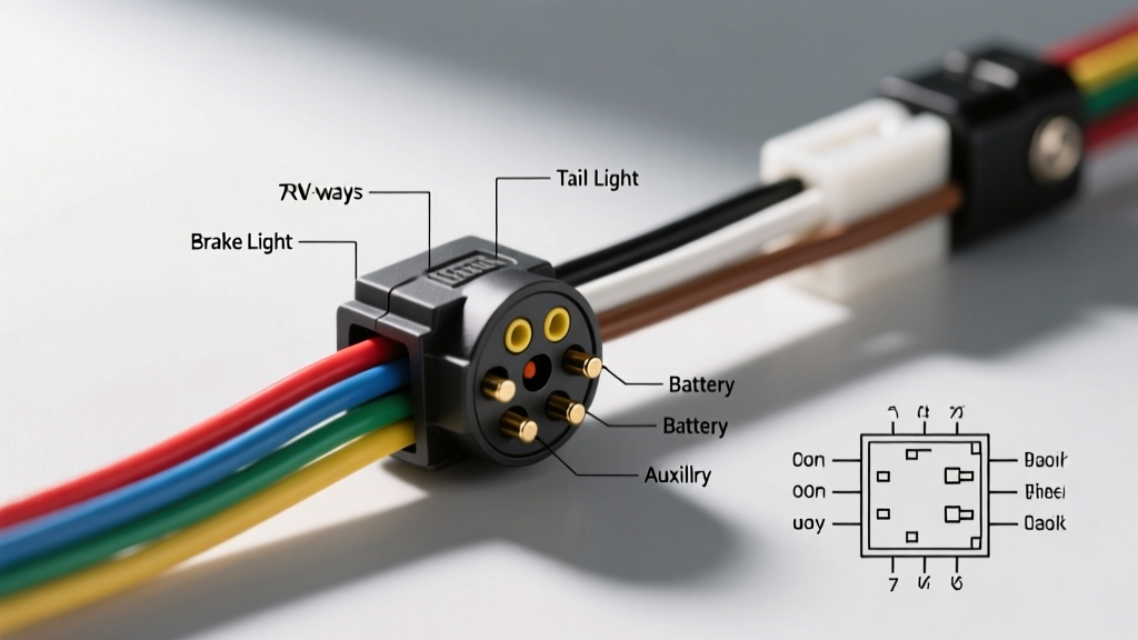
The physical layout of the 7-way RV blade connector places the ground pin at the bottom (6 o'clock position) to prevent water ingress from dripping onto the primary power terminals. Below is the standardized pinout matrix detailing the exact terminal assignments, OEM wire color codes, and primary circuit functions.
| Pin / Clock Position | Circuit Function | Standard Wire Color | Terminal Type |
|---|---|---|---|
| Pin 1 (6 o'clock) | Chassis Ground (White) | White | Ring Terminal / Chassis |
| Pin 2 (2 o'clock) | Electric Trailer Brakes | Blue | Blade Spade |
| Pin 3 (10 o'clock) | Tail / Running / Marker Lights | Brown | Blade Spade |
| Pin 4 (9 o'clock) | Left Turn Signal / Stop Lamp | Yellow | Blade Spade |
| Pin 5 (12 o'clock) | 12V Auxiliary Power / Battery Charge | Black | Blade Spade |
| Pin 6 (3 o'clock) | Right Turn Signal / Stop Lamp | Green | Blade Spade |
| Pin 7 (4 o'clock) | Reverse Lamps / Backup Solenoid | Red or Purple | Blade Spade |
Note: While SAE standards dictate these colors, some aftermarket European imports or custom fleet harnesses may utilize DIN 47002 color codes. Always verify continuity with a digital multimeter (DMM) before finalizing termination.
Wire Gauge (AWG) and Ampacity Requirements
A critical error when executing a diagram of wiring a plug is undersizing the wire gauge. The 12-volt DC automotive electrical system requires thicker conductors than equivalent 120-volt AC household wiring to mitigate voltage drop over the 20-to-30-foot run from the vehicle battery to the trailer axle. According to Curt Manufacturing's towing electrical guidelines, the following AWG specifications must be strictly adhered to for safe thermal operation.
| Circuit | Minimum AWG Size | Max Continuous Amperage | Recommended Fuse / Breaker |
|---|---|---|---|
| Ground (White) | 10 AWG | 40A | N/A (Main System Ground) |
| Electric Brakes (Blue) | 12 AWG (10 AWG preferred) | 20A - 30A | 30A Auto-Reset Breaker |
| 12V Auxiliary (Black) | 10 AWG | 30A | 40A Auto-Reset Breaker |
| Tail / Running (Brown) | 16 AWG | 10A | 15A Mini Fuse |
| Turn / Stop (Yellow/Green) | 14 AWG | 15A | 20A Mini Fuse |
| Reverse (Red/Purple) | 14 AWG | 15A | 15A Mini Fuse |
Grounding Protocols and Chassis Integration
The white ground wire (Pin 1) is the most common point of failure in trailer wiring. It must not be grounded to the trailer hitch ball or bumper, as paint, rust, and pivot friction create high resistance. The 10 AWG white wire must be terminated with a closed-loop ring terminal, secured to bare, sanded chassis metal using a stainless steel bolt and a star washer. The connection should be torqued to 15-20 in-lbs and coated with a marine-grade dielectric grease to prevent galvanic corrosion between dissimilar metals.
Vehicle-Specific Harness Integration (BCM & Multiplexing)
Modern vehicles (2015-present Ford F-150, Ram 1500, Chevrolet Silverado) do not send raw 12V battery power to the tail light bulbs. Instead, the Body Control Module (BCM) utilizes Pulse Width Modulation (PWM) or multiplexed CAN-bus signals to monitor bulb resistance and detect outages. If you tap directly into these low-current BCM wires to feed a 7-way plug, the trailer's combined resistance will confuse the BCM, triggering a 'Trailer Wiring Fault' message on the dash and disabling the circuit.
To correctly integrate a 7-way plug into a modern multiplexed vehicle, you must use a powered converter module (such as the Tekonsha 119190ZEX or equivalent). This module uses the vehicle's PWM tail light wires merely as a signal trigger (drawing less than 5mA), while a dedicated 12 AWG black wire run directly to the vehicle battery provides the actual high-current 12V power to the trailer plug. This isolates the trailer's electrical load entirely from the vehicle's sensitive BCM.
Crimping and Environmental Sealing Standards
Standard vinyl-insulated butt connectors are strictly prohibited for exterior automotive trailer wiring. Vibration and thermal cycling will cause the copper strands to oxidize and back out of the crimp barrel. The only acceptable termination method is the use of adhesive-lined polyolefin heat shrink butt connectors (e.g., 3M Scotchlok). When heated to 250°F (121°C), the internal thermoplastic adhesive melts and flows into the wire strands, creating a 100% waterproof, strain-relieved seal that blocks capillary action and green copper oxide formation.
Diagnostic Troubleshooting: Voltage Drop and Ground Loops
When a 7-way plug malfunctions, replacing parts blindly is inefficient. Use the following diagnostic decision tree to isolate the root cause using a Digital Multimeter (DMM).
| Symptom | Probable Cause | Diagnostic Step | Correction Protocol |
|---|---|---|---|
| Trailer running lights dim when brake is applied. | Ground Loop / High Resistance on Pin 1. | Measure voltage drop between vehicle battery negative and trailer plug Pin 1 under load. A reading >0.2V indicates a bad ground. | Sand chassis ground point, apply star washer, and upgrade to 10 AWG wire. |
| Electric brakes pulse erratically or fail to engage. | Voltage drop on Blue wire or corroded PK12706 spade. | Check continuity of Blue wire. Inspect Pin 2 for green oxidation. Measure voltage at trailer axle magnet (should be 11.5V+ at max controller gain). | Clean spade terminals with contact cleaner; replace auto-reset breaker if tripping prematurely. |
| Left turn signal stays solid or hyper-flashes. | BCM fault or short in Yellow wire. | Disconnect trailer. Test vehicle-side Pin 4 for 12V pulsing. If solid 12V, converter module has failed. If no voltage, check upstream BCM fuse. | Replace powered converter module; inspect yellow wire for chafing near hitch receiver. |
| 12V Auxiliary (Pin 5) reads 9V at trailer battery. | Undersized wire or corroded inline breaker. | Perform voltage drop test from vehicle battery positive to Pin 5. A drop >0.5V confirms conductor or breaker resistance. | Upgrade Black wire to 8 AWG for long-bed trucks; replace 40A breaker with sealed marine-grade unit. |
Final Verification and Load Testing
After executing the diagram of wiring a plug and completing all terminations, a static continuity test is insufficient. You must perform a dynamic load test. Connect the trailer, start the tow vehicle, and activate all lighting circuits simultaneously. Use an infrared thermal camera to scan the 7-way plug housing and the inline auto-reset breakers. Any terminal or breaker exhibiting a temperature delta greater than 20°F (11°C) above ambient indicates a high-resistance connection that will eventually melt the plug housing or cause a thermal fire. Properly executed 7-way wiring should remain cool to the touch even under maximum electric brake and auxiliary charging loads.