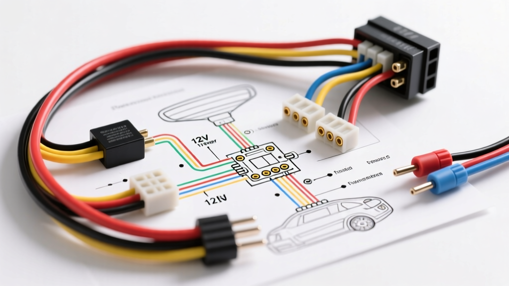
Understanding the Core Logic of Motorized Masts
Installing a motorized mast requires more than just connecting positive and negative terminals. When consulting a wiring diagram for power antenna systems, the most critical distinction you must make is whether you are dealing with a 3-wire aftermarket latching system or a 5-wire OEM direct-drive system. Misinterpreting these diagrams is the leading cause of burnt-out motors, melted head unit trigger circuits, and parasitic battery draws.
Unlike a fixed mast, a power antenna relies on a reversible DC motor connected to a spool that winds a flexible nylon toothed cord. The electrical circuit must not only provide the amperage required to drive the motor under load but also incorporate a method to cut power once the mast reaches its physical limits to prevent motor burnout. This is achieved either through internal magnetic slip clutches paired with latching relays (aftermarket) or micro-switch limit breakers (OEM).
Decoding the Wiring Diagram for Power Antenna Systems
The Standard 3-Wire Aftermarket Setup
Most universal replacement antennas (such as those from Autotek or Scosche) utilize a 3-wire harness. This setup is designed to interface seamlessly with the standard 'Power Antenna' or 'Amp Turn-On' lead found on aftermarket head units.
- Red Wire (Constant 12V+): Supplies the primary current for the motor. This must be connected to a fused, battery-direct constant 12V source.
- Black Wire (Chassis Ground): Completes the motor circuit. Must be grounded to bare, unpainted chassis metal.
- Blue/White Wire (12V Trigger): Connects to the head unit's remote turn-on lead.
Technical Insight: How does a 3-wire antenna know when to go down if there is no separate 'down' trigger wire? Inside the motor housing is a bi-stable latching relay. When the radio turns on, 12V is sent to the Blue/White wire, energizing the relay coil and switching the motor polarity to 'Up'. When the radio turns off, the trigger drops to 0V. The latching relay physically switches states, reversing the motor polarity to 'Down' and drawing power from the constant Red wire until the internal limit switch breaks the circuit.
The 5-Wire OEM Setup (GM/Ford/Toyota)
Factory power antennas, particularly prevalent in 1990s and early 2000s General Motors vehicles (e.g., C4/C5 Corvette, GMT400 trucks), use a 5-wire direct-drive system. The head unit or a dedicated amplifier module handles the logic, sending discrete signals for up and down commands.
- Orange (Constant 12V+): Primary motor power.
- Black (Ground): Chassis ground.
- Gray (Up Trigger): Receives 12V from the radio/amp to extend the mast.
- Brown (Down Trigger): Receives 12V from the radio/amp to retract the mast.
- Shield/Drain (Bare or Black/White): RF interference shield, grounded at the head unit end only.
In this configuration, the motor assembly contains two physical limit switches. When the mast reaches full extension, the 'Up' limit switch opens, cutting power to the Gray circuit even if the head unit is still commanding it to rise.
Electrical Specifications and Material Requirements
Using the correct wire gauge and over-current protection is non-negotiable. Power antenna motors draw between 3A and 5A during startup (stall current) and 1.5A to 2A during normal operation. Voltage drop over long wire runs to the trunk or quarter panel can cause the motor to stall prematurely.
| Circuit Function | Aftermarket Color | GM OEM Color | Min. AWG Size | Fuse Rating | Connector Type |
|---|---|---|---|---|---|
| Constant 12V+ Feed | Red | Orange | 14 AWG | 10A ATO/ATC | Solder-Seal Heat Shrink |
| Chassis Ground | Black | Black | 14 AWG | N/A | 16-14 AWG Ring Terminal |
| Up Trigger / Remote | Blue/White | Gray | 18 AWG | N/A (Radio fused) | Crimp Cap / Heat Shrink |
| Down Trigger (OEM) | N/A | Brown | 18 AWG | N/A | Crimp Cap / Heat Shrink |
Step-by-Step Installation Guide
- Disconnect the Battery: Always isolate the negative battery terminal before tapping into the vehicle's constant 12V or ignition circuits to prevent shorting the B+ bus bar.
- Route the Constant Power and Fuse: Run a 14 AWG primary wire from the battery or a known constant 12V distribution block in the trunk. Install an inline 10A ATO fuse holder within 18 inches of the power source. Splice this to the antenna's Red (or Orange) wire using adhesive-lined solder-seal heat shrink connectors.
- Establish a True Chassis Ground: Do not ground the Black wire to a seatbelt bolt or a painted trunk hinge. Locate a factory ground stud or drill a 1/4-inch hole in the inner quarter panel. Sand the area down to bare, shiny metal using 80-grit sandpaper. Crimp a vinyl-insulated 14 AWG ring terminal (using an IWISS SN-28B or equivalent ratcheting crimper), bolt it to the chassis, and coat the terminal in dielectric grease to prevent galvanic corrosion.
- Identify and Splice the Trigger Wire: If using an aftermarket head unit, locate the Blue/White 'System Remote Control' wire. If you are integrating into a factory Bose/Delco amplified system, you must use a relay. The factory amplifier turn-on lead often provides less than 300mA, which is insufficient to reliably trigger some aftermarket antenna latching relays over time. Use the factory signal to trigger a standard 30A automotive SPST relay, and use the relay's switched 12V output to trigger the antenna's Blue/White wire.
- Test Before Final Assembly: Reconnect the battery and turn on the head unit. Verify the mast extends fully and stops. Turn the radio off and verify it retracts fully. Listen for the internal limit switch 'click' or the slip clutch whirring sound indicating the cycle is complete.
Diagnostic Flowchart: When the Mast Fails to Operate
Even with a perfect wiring diagram for power antenna integration, mechanical and electrical failures occur. Use this diagnostic tree to isolate the fault:
- Symptom: Motor hums, but mast does not extend or retract.
- Cause: The internal nylon toothed cord has stripped or snapped. The motor is spinning the spool, but it is no longer gripping the mast.
- Fix: Disassemble the motor housing, clean out the old cord debris, and install a replacement universal nylon mast cord and spool kit.
- Symptom: Motor runs continuously after the mast reaches the top or bottom.
- Cause: In a 5-wire OEM system, the internal micro-limit switch has failed or become clogged with carbon dust. In a 3-wire system, the internal latching relay contacts have welded together due to arcing.
- Fix: For OEM, replace the motor assembly (limit switches are rarely serviceable separately). For aftermarket, replace the unit, as the latching relay is sealed in epoxy.
- Symptom: Mast goes up, but will not go down when the radio is turned off.
- Cause: Loss of ground, or the trigger wire is spliced into a 'Switched Accessory' (Ignition) 12V source instead of the head unit's dedicated remote lead. If the radio is turned off but the key remains in the 'ACC' position, the trigger wire remains hot, holding the latching relay in the 'Up' state.
- Fix: Verify the Blue/White trigger wire is connected strictly to the head unit's remote output, which drops to 0V the moment the radio powers down, regardless of ignition position.
Authoritative References and Further Reading
For advanced troubleshooting of factory amplified systems and data-bus trigger integration, consult the Metra Electronics installation guides, which provide vehicle-specific harness pinouts and resistance values. When diagnosing continuous motor runtime and parasitic draws, the AA1Car power antenna diagnostic archives offer excellent multimeter testing procedures for OEM limit switches. Finally, ensure your physical mounting and grounding torque specs align with standard Haynes antenna replacement procedures to prevent water intrusion into the trunk cavity, which is the leading cause of premature motor housing corrosion.