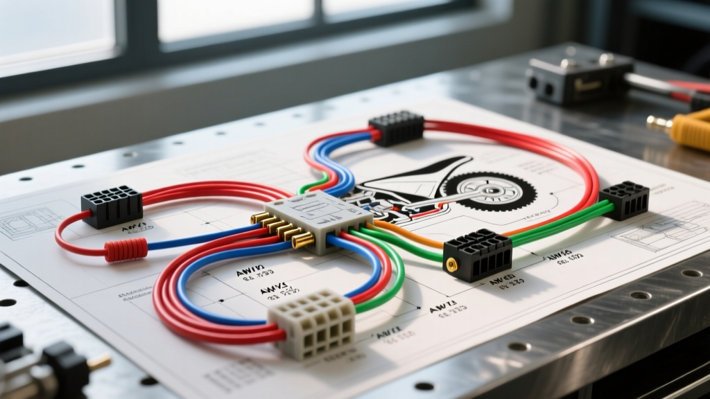
The Reality of Pit Bike Electrical Systems
If you have ever tried to trace a short circuit on a 125cc or 140cc mini moto, you already know that finding an accurate, factory-issued wiring diagram for pit bike models is nearly impossible. Manufacturers of popular platforms like SSR, Kayo, BSE, and Thumpstar frequently change electrical component suppliers mid-production year. The result is a chaotic mix of non-standardized wire colors, undersized gauges, and brittle PVC insulation that cracks after a single season of riding. Rather than attempting to decipher a melted OEM harness, the most reliable and cost-effective solution is to strip the bike to the frame and fabricate a custom harness based on a universal DC-CDI wiring diagram for pit bike applications.
Building a custom harness requires a specific set of automotive-grade tools and materials. This guide provides a comprehensive cost and tool requirements analysis for rewiring a standard horizontal-engine pit bike (50cc to 150cc), ensuring your electrical system can withstand high-RPM vibration, mud, and water exposure.
Essential Tool Requirements for Harness Fabrication
You cannot build a reliable motorcycle harness with a pair of needle-nose pliers and electrical tape. High-frequency vibration from a rigidly mounted, single-cylinder engine will quickly shake loose poorly crimped terminals, leading to intermittent ignition failure or stator burnout. Below is the required tooling for a professional-grade pit bike rewiring project.
| Tool | Specification / Model | Estimated Cost | Purpose |
|---|---|---|---|
| Ratcheting Crimper | IWISS SN-28B or Hozan P-707 | $25.00 - $65.00 | Crucial for crimping 1.5mm to 2.8mm JST, Molex, and bullet terminals without damaging the wire strands. |
| Precision Wire Strippers | Klein Tools 11055 (10-20 AWG) | $22.00 | Prevents nicking the copper strands, which creates weak points prone to snapping under chassis vibration. |
| Digital Multimeter | Innova 3320 or Fluke 87V | $25.00 - $250.00 | Required for testing stator AC output, checking continuity on the kill switch circuit, and verifying DC rectifier output. |
| Heat Shrink Torch | Mini Butane Heat Gun | $15.00 | Shrinking adhesive-lined marine heat shrink over crimp joints to seal out moisture and prevent corrosion. |
Total Tool Investment: $87.00 - $352.00 (depending on multimeter selection). For most DIY mechanics who already own a multimeter, the specialized crimping and stripping tools will cost under $50.
Material Cost Breakdown: Wire, Connectors, and Components
When referencing a universal wiring diagram for pit bike builds, you must select the correct wire gauge. According to SAE J1128 standards for low-tension primary cables, you should always use TXL or GXL (cross-linked polyethylene) wire rather than standard PVC. TXL wire features a thinner insulation wall, allowing for tighter routing in the pit bike's cramped head tube and steering stem area, while offering superior heat and abrasion resistance.
| Material | Specification | Estimated Cost |
|---|---|---|
| TXL Primary Wire | 16 AWG (Red, Black, Yellow, Blue) - 25ft spools | $45.00 |
| TXL Heavy Wire | 14 AWG (Red, Black) - For battery/starter feeds | $18.00 |
| Terminal Connectors | 2.8mm Bullets, 4-pin/6-pin JST, Weatherpack | $25.00 |
| DC CDI & Rectifier | Aftermarket 6-pin DC CDI & 4-pin Half-Wave Rectifier | $35.00 |
| Wire Loom & Tape | Split loom, Tesa cloth tape, 3M adhesive heat shrink | $22.00 |
| Fuses & Holders | Inline ATC fuse holders, 10A and 15A ATC fuses | $12.00 |
Total Material Cost: Approximately $157.00. This is significantly cheaper than purchasing a fragile, pre-made OEM replacement harness (which often exceeds $120 and requires splicing anyway) and yields a vastly superior, weather-sealed result. Sourcing high-quality wire from established suppliers like Delcity Wire ensures you are getting pure copper stranding rather than copper-clad aluminum (CCA), which suffers from severe voltage drop over distance.
Decoding the Generic Pit Bike Stator and CDI Pinouts
The most confusing aspect of following a wiring diagram for pit bike restorations is the stator-to-CDI interface. Most 110cc to 150cc horizontal engines utilize a 6-pin DC CDI and a 4-wire or 5-wire stator. Below is the industry-standard pinout configuration for a 6-pin DC CDI, which you must adhere to when fabricating your harness.
6-Pin DC CDI Pin Configuration
- Pin 1 (12V+ Battery Feed): Red wire. Connects to the main ignition switch 12V output and the primary fuse block. Provides power to the CDI capacitor.
- Pin 2 (Ground): Black wire. Must be grounded directly to the engine case or a dedicated, sanded-down frame grounding point. Do not rely on rusty frame bolts for ECU grounds.
- Pin 3 (Pulse Coil / Pickup): Blue/White wire. Carries the low-voltage trigger signal from the stator's pickup coil to tell the CDI when to fire.
- Pin 4 (Ignition Coil Trigger): Black/Yellow wire. The high-voltage discharge output from the CDI to the primary side of the ignition coil.
- Pin 5 (Stator Lighting/Trigger): Green wire. Often tied to the stator's lighting coil or secondary trigger depending on the specific magneto flywheel setup.
- Pin 6 (Kill Switch): White/Green wire. Connects to the handlebar kill switch. When the switch is closed, this pin is grounded, shorting the CDI and stopping the spark.
Stator Output Analysis and Rectifier Sizing
When designing your harness, you must account for the stator's wattage. Most stock pit bike stators output between 35W and 50W of alternating current (AC). The yellow wire typically carries AC power directly to the headlight, while the white/pink wire feeds the rectifier to charge the 12V battery.
If you are upgrading to modern LED lighting (which requires DC power), you must bypass the OEM AC headlight switch. You will need to route the stator's charging coil directly into a full-wave or heavy-duty half-wave rectifier, converting all AC output to DC, and then route that DC power through a relay to your LED headlight. According to technical guidelines from Electrosport Industries, exceeding the stator's wattage rating with auxiliary lights will cause the battery to drain at idle, eventually leading to CDI failure due to low-voltage starvation. Always calculate your total DC draw (headlight, taillight, EFI pump if applicable) and ensure it remains at least 15% below the stator's peak wattage output.
Common Pit Bike Wiring Failure Modes & Preventative Routing
Even with a perfect wiring diagram for pit bike electronics, the physical routing of the harness dictates its lifespan. Pit bikes endure extreme physical abuse. Here are the most common failure modes and how to engineer them out of your custom build:
1. Steering Stem Chafing
The Failure: The OEM harness is often zip-tied too tightly near the steering stem. When the handlebars are turned to full lock, the wires stretch, fray, and short against the frame, blowing the main fuse or killing the engine.
The Fix: Create a deliberate 'service loop' (an extra 3 inches of slack) wrapped in Tesa cloth friction tape just below the lower triple clamp. This allows the harness to flex smoothly without pulling on the crimp terminals inside the headlight bucket.
2. Stator Wire Fatigue at the Engine Case
The Failure: The wires exiting the left-side stator cover are subjected to intense heat and vibration. The PVC insulation melts against the exhaust header, or the copper strands snap inside the insulation.
The Fix: Use fiberglass sleeve wire loom (rated for 1000°F) over the stator wires from the engine case grommet to the main harness split. Secure the wires with stainless steel P-clips and rubber grommets, avoiding plastic zip-ties which become brittle and snap under engine vibration.
3. Rectifier Overvoltage
The Failure: Running the pit bike without a battery (or with a dead battery) on a DC-CDI system causes the rectifier's output voltage to spike well over 18V, instantly frying the CDI unit and LED bulbs.
The Fix: Always wire a high-quality 12V sealed AGM or Lithium battery into the circuit to act as a voltage sink/buffer. Install an inline 10A ATC fuse on the main positive battery feed to protect the harness in the event of a rectifier short.
Conclusion
Relying on a factory wiring diagram for pit bike repairs is often an exercise in frustration due to poor manufacturing consistency and substandard materials. By investing roughly $200 in TXL automotive wire, ratcheting crimpers, and weather-sealed connectors, you can build a custom harness that outperforms and outlasts the OEM setup. Understanding the 6-pin CDI logic, managing stator wattage limits, and implementing vibration-resistant routing techniques will ensure your mini moto starts on the first kick, every time.