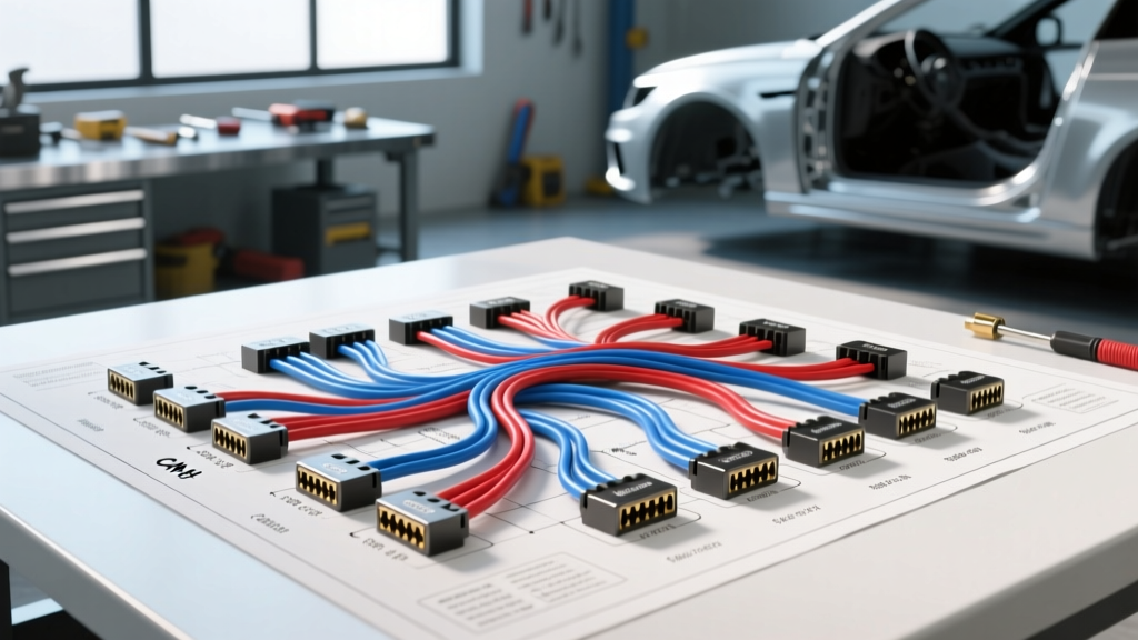
Beyond Basic Power: The Modern Aftermarket Stereo Wiring Diagram
When enthusiasts and professional installers search for a wiring diagram for aftermarket stereo integration, they are frequently met with outdated, generic 1990s color-code charts. While the EIA/CEA-315 standard still dictates basic aftermarket wire colors—Yellow for 12V constant, Red for 12V switched, and Black for chassis ground—modern vehicle architecture has rendered these simplistic diagrams insufficient. Today’s late-model vehicles rely on multiplexed data networks (CAN-bus, LIN-bus, and GMLAN) to manage ignition states, illumination, and amplifier wake-up sequences. Attempting to wire a modern DSP-equipped head unit using only a standard 12V ignition tap will result in parasitic battery draws, DSP brownouts, and severe data-bus sleep interference.
This advanced technical deep dive explores the true schematic requirements for integrating an aftermarket head unit into a modern CAN-bus architecture, managing high-level differential audio signals, and bypassing Active Noise Cancellation (ANC) systems without inducing low-frequency feedback loops.
Decoding the CAN-Bus Data Harness Pinout
In vehicles manufactured after 2008, the traditional 'Red' ignition wire is often entirely absent from the OEM radio harness. Instead, the Body Control Module (BCM) or Infotainment Master broadcasts an 'Ignition Run/Start' status message over the CAN network. To interface an aftermarket stereo, a CAN-bus decoding module (such as those from PAC, Axxess, or Maestro) must be spliced into the correct network topology.
Crucially, installers must distinguish between High-Speed CAN (Powertrain/Chassis)Medium-Speed or Comfort CAN (Infotainment/Body). Tapping into the High-Speed network (typically found at the OBD2 port on Pins 6 and 14) to wake up a stereo can cause severe network contention and throw U-codes (e.g., U0155 - Lost Communication with Instrument Panel Cluster). The wiring diagram for your specific aftermarket stereo interface will dictate tapping the Infotainment CAN lines, which operate at different baud rates (typically 125 kbps to 500 kbps) and utilize different physical layer voltages.
| Network Type | Wire Designation | Recessive State (Idle) | Dominant State (Active) | Differential Voltage |
|---|---|---|---|---|
| Standard CAN-Bus | CAN-High | 2.50V | 3.50V | +2.0V |
| Standard CAN-Bus | CAN-Low | 2.50V | 1.50V | -2.0V |
| GM Single-Wire (GMLAN) | GMLAN Data | 0.00V | 3.50V | N/A (Single Wire) |
According to the CAN in Automation (CiA) physical layer specifications, the CAN network requires a 120-ohm termination resistor at each end of the bus. When splicing a stereo interface harness, you must use high-impedance solder joints or ultrasonic welds; using standard crimp caps can introduce capacitance that reflects high-frequency signals, leading to intermittent data dropouts and radio reboots.
High-Level Signal Summing and OEM Amplifier Bypass
If the vehicle is equipped with an OEM amplified system (e.g., Bose, Harman Kardon, Mark Levinson), the wiring diagram for the aftermarket stereo must account for high-level differential signals and Class-D amplifier summing. OEM amplifiers often output bridged, differential signals where neither the positive nor negative speaker wire is referenced to chassis ground. Connecting a standard aftermarket head unit's RCA pre-outs to these lines via a basic Line Output Converter (LOC) will result in severe clipping and potential short circuits.
Active Noise Cancellation (ANC) Bypass Protocols
Modern vehicles utilize ANC and Road Noise Cancellation (RNC) microphones that feed inverted-phase audio signals to the OEM amplifier to cancel out engine drone (typically between 20Hz and 150Hz). When you bypass the OEM amplifier and introduce an aftermarket DSP, the ANC microphone remains active. The aftermarket DSP will attempt to sum and process this inverted phase signal, resulting in a violent, low-frequency howling feedback loop that can instantly destroy aftermarket subwoofers.
- Hardware Delete: Physically disconnect the ANC microphone module located in the overhead console and terminate the OEM mic wiring harness with a 2.2kΩ resistor to prevent the BCM from throwing a diagnostic trouble code (DTC).
- Data-Link Mute: Advanced interface modules (like the idatalink Maestro) can send a CAN-bus payload to the ANC module commanding a 'Mute' state upon detecting the aftermarket radio's power-up sequence.
Steering Wheel Control (SWC): Resistor Ladders vs. CAN Messages
Retaining steering wheel controls requires understanding how the OEM clock spring communicates button presses. Older vehicles and specific Asian platforms use an analog resistor ladder network. The wiring diagram will show two wires: SWC Key 1 and SWC Key 2. Pressing a button completes a circuit through a specific resistor, dropping the reference voltage (usually 3.3V or 5V) to a measurable analog value.
| Button Function | Measured Resistance | ADC Voltage Drop (3.3V Ref) |
|---|---|---|
| Volume Up | 0Ω (Short) | 0.00V |
| Volume Down | 300Ω | 0.45V |
| Track Forward | 1,000Ω | 1.15V |
| Track Back | 3,000Ω | 2.10V |
In contrast, late-model European and domestic vehicles transmit SWC button presses as digital CAN-bus messages (e.g., LIN-bus sub-nodes on the steering column module). Analog SWC interfaces will not work here; a digital data translator is mandatory to read the hex codes and translate them into the proprietary IR or wired protocols required by the aftermarket stereo.
Wire Gauge (AWG) and Current Draw Best Practices
A critical, often overlooked aspect of the aftermarket stereo wiring diagram is the power delivery gauge. Standard aftermarket harnesses utilize 18 AWG wire for the Yellow (Constant 12V) and Red (Switched 12V) leads. However, modern multimedia receivers with built-in Class-D amplifiers and heavy DSP processing can draw peak currents exceeding 15 Amps. According to SAE J1128 standards for Low Tension Primary Cable, 18 AWG wire is only rated for roughly 10-14 Amps depending on the insulation temperature rating and bundling factor.
When voltage sag drops below 11.8V at the head unit's power pins, the internal DSP will trigger a brownout protection sequence, causing the unit to reboot randomly during heavy bass transients. Best Practice: Splice a 14 AWG or 12 AWG primary automotive wire directly to the Yellow constant wire within 6 inches of the head unit harness, and route it directly to the vehicle battery with an inline 15A or 20A ATO fuse. Bypass the OEM radio fuse panel, which is often shared with the BCM and cannot handle the transient inrush current of large aftermarket capacitors.
Troubleshooting Parasitic Draw and Data Bus Sleep
The most common failure mode in advanced installations is the 'Data Bus Awake' parasitic draw. If the aftermarket stereo's CAN-bus interface is wired incorrectly, it may continuously broadcast or fail to acknowledge the BCM's 'Sleep' command when the vehicle is locked. This keeps the entire CAN network active, drawing 300mA to 800mA continuously, which will kill a standard lead-acid battery in 48 hours.
Diagnostic Decision Tree for Parasitic Draw
- Measure Quiescent Current: Use a digital multimeter in series with the negative battery terminal. Wait 20 minutes for all modules to enter sleep mode. Target draw should be < 50mA.
- Isolate the Interface: If draw remains > 100mA, disconnect the data-link harness (CAN-H / CAN-L) from the aftermarket stereo interface. If the draw drops to normal, the interface is failing to sleep.
- Check the 'Ignition Sense' Logic: Many interfaces have a secondary analog ignition sense wire (often Pink or Yellow/Red). If this is wired to a circuit that retains power (like an RAP - Retained Accessory Power circuit), the interface will never send the 'Power Down' command to the head unit.
- Verify CAN-H/CAN-L Polarity: Swapping CAN-High and CAN-Low will not always prevent communication (some transceivers are fault-tolerant), but it will corrupt the sleep-state termination resistors, keeping the physical layer biased and awake.
Mastering the true wiring diagram for an aftermarket stereo means looking past the basic 12V power chart and understanding the digital ecosystem of the modern vehicle. By respecting CAN-bus topologies, properly summing high-level differential signals, and sizing power wiring to SAE standards, you ensure a seamless, factory-grade integration that delivers uncompromised audio fidelity and reliable vehicle operation.
For further reading on automotive electrical standards, consult the Consumer Technology Association (CTA) guidelines on mobile electronics installation and SAE network topology documentation.