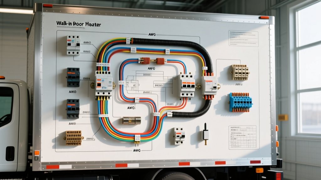
Commercial Transport Refrigeration: The Role of Door Heaters
When outfitting a commercial box truck, step van, or tractor-trailer with a transport refrigeration unit (TRU), maintaining compartment integrity is critical. In sub-zero applications, the door gasket can freeze to the steel or aluminum frame, causing severe tearing upon opening and compromising the thermal envelope. To prevent this, fleet managers and upfitters rely on a dedicated perimeter heating element. Understanding the walk in freezer door heater wiring diagram is essential for mobile mechanics, fleet electricians, and upfit technicians working on vehicle-mounted cold storage systems. This guide provides a comprehensive cost and tool requirements analysis for installing, diagnosing, and repairing 12V DC and 24V DC door heater circuits on commercial refrigerated vehicles.
Walk In Freezer Door Heater Wiring Diagram: 12V DC Circuit Architecture
Unlike stationary commercial HVAC systems that utilize 120V or 208V AC line power, vehicle-mounted walk-in freezer bodies (such as those built on Morgan Olson, Workhorse, or Freightliner chassis) typically utilize the vehicle's 12V DC electrical system or the TRU's internal alternator output to power the door frame heater. The walk in freezer door heater wiring diagram for a standard 12V DC truck application follows a heavy-duty relay-switched architecture to prevent overloading the cab's auxiliary switch panel.
Schematic Flow and Component Routing
- Power Source: 12V DC from the chassis battery bank or TRU auxiliary battery, routed through a 30A MIDI or Mega fuse mounted within 18 inches of the positive terminal.
- Primary Circuit (Load): 10 AWG primary wire (SAE J1128 compliant) feeds Pin 30 of a heavy-duty 40A Bosch-style automotive relay.
- Secondary Circuit (Switched Load): Pin 87 of the relay routes 12V+ directly to the positive terminal of the door heater element via a waterproof Deutsch DT connector.
- Control Circuit (Trigger): Pin 86 receives a 12V+ trigger signal from the freezer compartment's digital thermostat controller (activated only when compartment temps drop below 10°F).
- Ground Circuit: Pin 85 of the relay and the negative terminal of the heater element are tied to the vehicle chassis ground using 10 AWG wire and a star-washer ring terminal.
Required Tooling & Diagnostic Equipment
Executing this wiring requires precision and adherence to commercial vehicle standards. Standard household electrical tools will fail under the high-vibration, high-moisture environment of a refrigerated truck body. Below is the required tooling analysis for a professional-grade installation or repair.
Essential Diagnostic & Crimping Tools
- True RMS Digital Multimeter (e.g., Fluke 87V): Required for accurate voltage drop testing and resistance measurements on the heater element. Cost: ~$450.
- Deutsch Crimp Tool (e.g., TE Connectivity YDT-4200): Essential for crimping solid DT series contacts. Improper crimps lead to moisture ingress and rapid galvanic corrosion. Cost: ~$220.
- Heat Gun with Reflector Nozzle: For shrinking dual-wall, adhesive-lined heat shrink tubing over inline splices. Cost: ~$85.
- Wire Stripper (Knipex ErgoStrip): To strip 10 AWG to 14 AWG cross-linked polyethylene (XLPE) jacketed wire without nicking the copper strands. Cost: ~$160.
- Torque Screwdriver: For securing ground ring terminals to the chassis or TRU frame. Over-torquing strips aluminum threads; under-torquing causes high-resistance ground faults. Cost: ~$120.
Material & Labor Cost Analysis
Whether you are a fleet manager budgeting for a retrofit or an independent mobile tech quoting a repair, understanding the material and labor costs associated with the walk in freezer door heater wiring diagram is vital. Dealership labor rates for commercial truck electrical work frequently exceed $165 per hour, making in-house fleet maintenance highly cost-effective.
| Component / Material | Specification | Estimated Cost (USD) |
|---|---|---|
| Silicone Door Heater Pad | 12V DC, 144W, 60-inch perimeter | $85.00 - $120.00 |
| Primary Wire (10 AWG) | SAE J1128, XLPE, Red/Black (50ft) | $45.00 |
| Control Wire (14 AWG) | SAE J1128, Blue (50ft) | $25.00 |
| Heavy Duty Relay | 12V 40A, 4-Pin, Sealed | $18.00 |
| Deutsch DT Connectors | DT04-2P & DT06-2S with wedgelocks | $12.00 (pack) |
| MIDI Fuse & Holder | 30A, 32V DC rated | $14.00 |
| Adhesive Heat Shrink | Dual-wall, 3:1 shrink ratio | $22.00 |
| Total Material Cost | $221.00 - $256.00 |
Labor Analysis: A complete teardown of the door gasket, removal of the old heater pad, routing of new 10 AWG wire through the articulated door hinges (using a flexible loom), and termination of the Deutsch connectors typically takes 3.5 to 4.5 hours. At an independent shop rate of $120/hr, labor costs range from $420 to $540. Total out-the-door cost for a professional repair is approximately $750, whereas a DIY fleet tech costs the company roughly $250 in materials and internal hourly overhead.
Pinout Configurations and Wire Color Codes
Adhering to standard commercial vehicle color codes ensures that future technicians can safely troubleshoot the circuit. According to SAE J1128 and standard Morgan Olson body builder guidelines, the following color codes and pinouts should be strictly maintained:
- Pin 30 (Relay Input): 10 AWG RED wire (Constant 12V+ from Battery/Fuse).
- Pin 87 (Relay Output): 10 AWG RED wire with a BLACK tracer (Switched 12V+ to Heater Element Pin 1).
- Pin 86 (Relay Coil Trigger): 14 AWG BLUE wire (12V+ from Freezer Thermostat Controller).
- Pin 85 (Relay Coil Ground): 14 AWG WHITE wire (Chassis Ground).
- Heater Element Pin 2 (Return): 10 AWG BLACK wire (Chassis Ground via DT connector).
The connection at the door frame must utilize a Thermo King / Carrier approved waterproof Deutsch DT06-2S plug. This allows the door to be removed or the heater pad replaced without cutting wires. The wedgelock must be fully seated to ensure the contacts do not back out under the vibration of highway transit.
Troubleshooting Decision Tree & Real-World Failure Modes
When a driver reports that the walk-in freezer door is freezing shut, or the TRU controller throws a 'Door Heater Fault' code, technicians must follow a systematic diagnostic path.
Step 1: Verify Heater Element Resistance
Disconnect the Deutsch DT connector at the door hinge. Set your Fluke multimeter to Ohms (Ω). Measure across Pin 1 and Pin 2 of the heater element side. A standard 144W, 12V heater draws 12 Amps. Using Ohm's Law (R = V / I), the expected resistance is 1.0 Ω.
Diagnostic Result: If the meter reads 'OL' (Open Loop), the internal nichrome wire is broken, requiring pad replacement. If it reads 0.0 Ω, the element is shorted internally.
Step 2: Voltage Drop Testing the Load Circuit
If resistance is correct (1.0 Ω) but the heater is not generating heat, perform a voltage drop test. Reconnect the Deutsch plug. With the freezer thermostat calling for heat (relay clicked ON), place your multimeter's red probe on the battery positive terminal and the black probe on the heater's positive pin (backprobe the connector).
Diagnostic Result: A reading greater than 0.5V indicates excessive resistance in the 10 AWG positive wire, usually caused by a corroded MIDI fuse holder or a failing relay contact. Repeat the test on the ground side (battery negative to heater negative pin). A ground-side voltage drop over 0.2V indicates a poor chassis ground connection, often caused by paint or rust under the star washer.
Step 3: Articulated Hinge Wire Fatigue
The most common failure mode in vehicle-mounted walk-in freezer door heaters is wire fatigue at the door hinge. The constant opening and closing of the heavy insulated door causes the 10 AWG wire to work-harden and eventually snap inside the insulation. To prevent this, always route the wiring through a flexible, braided nylon loom and leave a generous 'service loop' (an S-curve of slack) before securing the wire to the door frame with adhesive-backed cable ties. Never use standard zip-ties directly on the wire, as the sharp edges will cut into the XLPE jacket and cause a short to the aluminum door frame.