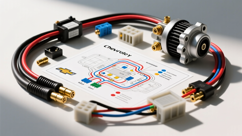
The Deceptive Simplicity of the Chevy 350 Starter Circuit
The Small Block Chevy (SBC) 350 is the most swapped, rebuilt, and restored engine in automotive history. Because of its ubiquity, enthusiasts often assume that hooking up the starter is a foolproof, two-wire affair. When reviewing a simple Chevy 350 starter wiring diagram, most builders see only a heavy battery cable and a single ignition trigger wire. However, this oversimplification is responsible for thousands of melted harnesses, fried ignition modules, and catastrophic electrical fires every year.
As an automotive electrical specialist, I see the same critical errors repeated in garages worldwide. The transition from points-style ignitions to High Energy Ignition (HEI) and modern EFI systems has fundamentally changed how the starter solenoid must be wired. This guide breaks down the exact specifications, common wiring traps, and vital safety warnings you must know before turning the key on your SBC 350.
Anatomy of the GM Delco Remy Starter Solenoid
To wire the system safely, you must understand the physical hardware. The standard GM starter solenoid (used on everything from 1960s muscle cars to 1990s trucks) features three primary external terminals. Confusing these terminals or using the wrong hardware is the root cause of most failures.
| Terminal ID | Thread / Hardware | Recommended AWG | OEM Wire Color | Function & Load Profile |
|---|---|---|---|---|
| B (Battery) | 3/8"-16 Stud | 2 AWG to 1/0 AWG | Red | Direct battery power. Carries 150A-250A during cranking. |
| S (Start) | 10-32 Machine Thread | 10 AWG or 12 AWG | Purple | Ignition switch trigger. Carries 15A-30A to pull the solenoid plunger. |
| R / I (Ignition) | 10-32 Machine Thread | 12 AWG or 14 AWG | Yellow (or Cloth) | Ballast resistor bypass. Provides 12V to coil ONLY during cranking. |
Pro-Tip: Many aftermarket "mini" starters use 3/8" nuts for all three terminals. Always verify thread pitch with a gauge before tightening. Forcing a 3/8" nut onto a 10-32 S-terminal will instantly strip the stud and crack the Bakelite insulator, causing a dead short to the starter housing.
Top 5 Wiring Mistakes on the Chevy 350 Starter
1. The R-Terminal Trap: Points vs. HEI Ignition
This is the most common and destructive mistake in SBC wiring. On older points-style ignitions, a ballast resistor wire drops the voltage to the coil to roughly 7V-9V during normal running to prevent point arcing. During cranking, voltage drops naturally, so the R-terminal on the solenoid sends a direct 12V bypass to the coil to ensure a hot spark.
The Mistake: Builders swap to an HEI distributor (which requires a full 12V at all times from a dedicated ignition source) but leave the R-terminal wire connected to the coil or ignition harness. When the starter engages, the R-terminal backfeeds 12V into the HEI module or EFI computer, potentially frying sensitive electronics or causing the engine to run even after the key is turned off (dieseling).
The Fix: If you are running HEI, MSD, or modern EFI, the R-terminal on the starter solenoid must be left completely empty and capped. Supply your HEI with a dedicated 12V switched source from the ignition switch or a relay.
2. Undersized Battery Cables and Voltage Drop
A standard OEM Chevy 350 starter draws about 150 amps. High-torque aftermarket mini-starters (like those from Powermaster or Tuff Stuff) can draw upwards of 200+ amps under load, especially on high-compression engines. Many builders reuse old, corroded 4 AWG or 6 AWG cables.
According to SAE J1141 standards for marine and heavy-duty electrical cables, voltage drop over a 6-foot run at 200 amps on a 4 AWG cable will exceed 1.5 volts. This starves the starter, causing heat soak and premature solenoid failure.
The Fix: Use a minimum of 2 AWG pure copper stranded cable for standard SBC 350s. If you are running a high-torque mini-starter or the battery is relocated to the trunk, upgrade to 1/0 AWG welding cable. Always use adhesive-lined heat shrink on all crimp lugs to prevent copper oxidation.
3. The Phantom Ground Path
The Chevy 350 starter grounds directly through its mounting bolts to the engine block. It does not have a dedicated ground wire. If the engine block mounting surface is painted, powder-coated, or heavily corroded, the starter will seek the path of least resistance to complete its massive 200-amp circuit.
The Consequence: The current will backfeed through the throttle linkage, heater hoses, or transmission shift cables, instantly welding throttle springs or melting rubber coolant hoses. I have personally seen a starter melt a braided stainless throttle cable because the block was painted without masking the starter ears.
The Fix: Always use a wire wheel or sanding disc to bare the cast iron on the starter mounting ears and the block. Additionally, verify that a minimum 2 AWG engine-to-chassis ground strap is securely bolted from a clean cylinder head bolt to the chassis.
4. Routing the Purple Trigger Wire Near Exhaust
The S-terminal trigger wire (OEM purple, 10 AWG) carries the signal from the ignition switch to the starter. On the Chevy 350, the starter sits directly beneath the passenger-side exhaust manifold or headers.
The Mistake: Routing the purple wire parallel to the exhaust pipe without heat shielding. The ambient heat from a 350 exhaust manifold easily exceeds 400°F, which will melt standard PVC wire insulation in minutes, causing the bare copper to short against the cast-iron starter housing. This results in the starter engaging randomly while driving.
The Fix: Route the S-terminal wire along the upper bellhousing or transmission tunnel. If it must pass near the headers, wrap the wire in fiberglass heat sleeving rated for 1,000°F and secure it with stainless steel zip ties.
5. Overtorquing and Cross-Threading Solenoid Nuts
The S and R terminals on an OEM Delco Remy solenoid pass through a fragile Bakelite or plastic insulator plate. Applying excessive torque, or using the wrong size wrench and slipping, will crack this insulator.
The Fix: The torque specification for the 10-32 S and R terminal nuts is incredibly low: just 35 to 50 inch-pounds. Use a 5/16" nut driver and tighten by hand. Never use a socket wrench or pliers on the small terminals.
Critical Safety Warnings Before Cranking
- Always Disconnect the Battery: Never install or remove the B-terminal cable while the battery is connected. A dropped wrench across the B-terminal and the starter housing will result in an immediate, violent dead-short capable of welding tools to metal and causing severe battery explosions.
- Cap the R-Terminal: If the R-terminal is unused (as with HEI), slide a piece of 1/4" heat-shrink tubing over the exposed stud. An exposed R-terminal can easily short against the exhaust heat shield or bellhousing.
- Use a Remote Starter Switch for Testing: When testing a newly wired Chevy 350 on an engine stand or in the bay, do not lean over the carburetor to turn the key. Use a handheld remote starter switch clipped to the B and S terminals, standing clear of the engine bay in case of backfires or accessory belt failures.
Step-by-Step Verification Checklist
Before applying main battery power, perform these continuity and resistance checks using a digital multimeter (DMM):
- B-Terminal Isolation: Set DMM to continuity. Place one probe on the B-terminal nut and the other on the starter metal casing. The meter should read OL (Open Loop). If it beeps, you have a crushed insulator or internal short. Do not connect the battery.
- S-Terminal Continuity: Place one probe on the S-terminal and the other on the solenoid pull-in coil ground (internal). You should read a low resistance (typically 1 to 3 ohms). If it reads OL, the solenoid coil is burned out.
- Voltage Drop Test (Post-Assembly): Once running, place your DMM in DC Volts. Put the red probe on the battery positive post and the black probe on the starter B-terminal nut while an assistant cranks the engine. A reading above 0.20V (200mV) indicates excessive resistance in the positive cable or connections. Repeat on the ground side (Battery Negative Post to Starter Housing). Max allowable drop is 0.20V.
Conclusion
While a simple Chevy 350 starter wiring diagram looks elementary on paper, the physical execution requires respect for high-amperage DC circuits. By selecting the correct AWG cable, eliminating the R-terminal on modern ignitions, and ensuring pristine grounding surfaces, you guarantee reliable starts and eliminate the risk of catastrophic electrical fires. For deeper diagnostics and factory schematic references, always consult Haynes Chevrolet repair manuals or OEM Delco Remy technical documentation specific to your vehicle's original chassis harness.