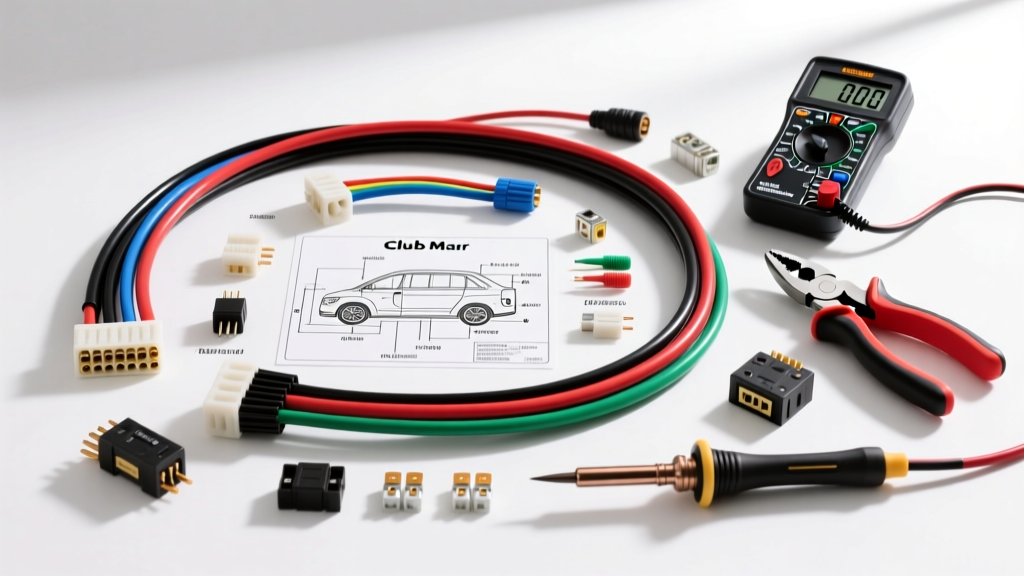
Decoding the Club Car Electrical Schematic: A Cost and Tool Analysis
Owning a factory Club Car electrical schematic for your DS, Precedent, or Onward model is the critical first step in diagnosing and repairing golf cart electrical systems. However, a wiring diagram is only as useful as the tools and materials you have on hand to execute the repairs. Whether you are troubleshooting a 36V PowerDrive system or upgrading a 48V IQ Precedent to lithium batteries, understanding the financial and tooling requirements is essential for fleet managers and DIY enthusiasts alike.
This comprehensive analysis breaks down the exact diagnostic equipment, wiring materials, and projected costs required to properly interpret and implement Club Car wiring schematics. We will focus heavily on the 48V Precedent IQ system, as its reliance on the Curtis 1268 motor controller and MCOR (Motor Controller Output Regulator) represents the most complex electrical architecture in the Club Car lineup.
Essential Diagnostic Tools & Budget Requirements
Interpreting a Club Car electrical schematic requires precise voltage and current measurements. Standard 12V automotive test lights are useless and potentially dangerous when probing 48V to 60V DC systems. To properly trace circuits from the key switch to the solenoid coil, you must invest in CAT-rated diagnostic equipment.
Multimeters and Clamp Meters
When reading the low-current control side of the schematic (typically 16 AWG wires handling 5V reference signals or 48V logic), a high-impedance digital multimeter (DMM) is mandatory. Cheap meters can load the circuit and cause the Curtis controller to throw an HPD (High Pedal Disable) fault code.
- True-RMS Digital Multimeter (CAT III 600V): Required for testing the 5V throttle signal at Pin 5 of the Curtis controller and checking for voltage drop across the OBC (Onboard Computer) relays. Estimated Cost: $250 - $400 (e.g., Fluke 87V or Fluke 117).
- DC Clamp Ammeter (600A+ Capacity): The schematic shows the main motor cables (2 AWG) routing directly from the controller to the motor. To diagnose a failing motor or seized brake, you must measure peak stall current without breaking the circuit. A standard multimeter will melt; a DC Hall-effect clamp meter is required. Estimated Cost: $120 - $180.
Wire Stripping and Crimping Equipment
Club Car schematics specify heavy-gauge cables for the high-current drive circuit. Attempting to crimp 2 AWG battery cables with standard pliers leads to high-resistance connections, resulting in melted terminals and severe voltage drop.
- Heavy-Duty Ratchet Crimper (8 to 2/0 AWG): Essential for applying 3/8-inch ring terminals to the main battery interconnects and motor studs. Estimated Cost: $45 - $85.
- Wire Stripper for 16-24 AWG: Needed for the delicate control harness wires (AMP Superseal and Molex connectors) connecting the F/R switch and MCOR. Estimated Cost: $25 - $40.
Material Costs: Wire Gauges, Terminals, and Connectors
A common mistake when following a Club Car electrical schematic is substituting Copper Clad Aluminum (CCA) wire for pure copper to save money. Golf carts draw massive continuous amperage (often 60A to 100A at cruising speeds), and CCA wire suffers from higher resistance and galvanic corrosion at the battery terminals. Always source pure OFC (Oxygen-Free Copper) or standard SAE J1128 compliant copper cable.
| Material / Component | Specification / AWG | Schematic Application | Est. Cost (USD) |
|---|---|---|---|
| Pure Copper Battery Cable | 2 AWG (Flexible Welding Cable) | Main B+ and Ground to Solenoid/Controller | $3.50 / ft |
| Primary Control Wire | 16 AWG (Multi-strand) | Key Switch, Solenoid Coil, F/R Switch | $0.45 / ft |
| Ring Terminals | 3/8 inch stud, 2 AWG | Motor studs and Battery posts | $1.20 / ea |
| Heat Shrink Tubing | 3:1 Ratio, Adhesive-lined | Terminal insulation to prevent shorting | $15.00 / kit |
| Replacement MCOR | OEM 48V IQ Throttle Box | Translates pedal travel to 0-5V signal | $110.00 - $140.00 |
| Heavy Duty Solenoid | 48V, 200A Continuous | Main high-current relay | $85.00 - $120.00 |
Schematic-Guided Repair Scenarios & Labor Analysis
Understanding the cost of parts is only half the equation. Applying the Club Car electrical schematic to real-world failure modes requires specific diagnostic sequences. Below are two of the most common, complex repairs encountered on 48V Precedent models.
Scenario 1: Precedent MCOR (Throttle) Diagnostics and Replacement
The MCOR is a non-contact Hall-effect or potentiometer-based sensor that dictates motor speed. The wiring schematic shows three primary wires leaving the MCOR harness: a 5V reference (Red/White), a Ground (Black), and the Signal Return (Blue/White) routing directly to Pin 5 on the Curtis 1268 controller.
The Failure Mode: Over time, the internal wiper track wears out, or moisture ingress causes signal fluctuation. This results in erratic acceleration or the cart entering 'limp mode' due to an HPD fault.
Diagnostic Steps & Costs:
- Backprobe the Signal Return wire with your DMM. With the key ON and the pedal at rest, voltage should be exactly 0.8V to 1.2V.
- Slowly depress the pedal. The voltage must climb smoothly to 3.8V - 4.2V without any dead spots or voltage spikes.
- If the voltage drops out mid-travel, the MCOR is defective. Do not attempt to repair the internal potentiometer; replace the unit.
Total Scenario Cost: $130 (OEM MCOR) + $15 (Dielectric grease and zip ties). Labor time for a schematic-literate technician is roughly 45 minutes.
Scenario 2: Solenoid and Pre-Charge Circuit Rebuild
The schematic for the 48V IQ system highlights a critical, often overlooked component: the pre-charge resistor and the flyback diode wired across the solenoid coil. When the key switch sends 48V down the 16 AWG Yellow wire to the small solenoid terminal, the coil pulls roughly 1.5 Amps to close the heavy internal contacts.
The Failure Mode: If the flyback diode fails open, the inductive voltage spike generated when the solenoid de-energizes will travel back through the wiring harness and fry the internal driver circuitry of the Curtis motor controller. Furthermore, pitting on the large 2 AWG terminals causes a voltage drop. According to Club Car technical service bulletins, a voltage drop greater than 0.2V across the closed solenoid under load dictates immediate replacement.
Repair Protocol:
- Remove the 3/8-inch nuts on the large terminals. Torque specification for reinstallation is 150-180 in-lbs to prevent arcing.
- Install the new solenoid. Ensure the diode band points toward the positive small terminal as explicitly drawn on the schematic.
- Verify the pre-charge resistor (typically 250 ohms, 5W) is intact. This resistor bleeds a small amount of current to pre-charge the controller capacitors before the main solenoid slams shut, preventing contact welding.
Total Scenario Cost: $95 (Solenoid with diode) + $12 (Pre-charge resistor) + $10 (Terminal anti-oxidant paste). Total parts: ~$117.
Wire Color Codes and Routing Standards
When fabricating a new harness based on a Club Car electrical schematic, adhering to OEM color codes is vital for future troubleshooting. While aftermarket kits often use generic colors, maintaining factory standards prevents catastrophic miswiring.
- Red (2 AWG): Main unswitched battery positive (B+).
- Black (2 AWG): Main battery negative (Ground).
- Blue (16 AWG): Key switch output (Switched 48V logic).
- Yellow (16 AWG): Solenoid coil activation.
- Green (16 AWG): Forward microswitch signal.
- White (16 AWG): Reverse microswitch signal.
Always route the 16 AWG low-current logic wires away from the 2 AWG motor cables. The electromagnetic interference (EMI) generated by the PWM (Pulse Width Modulation) frequency of the motor controller can induce ghost voltages in parallel control wires, leading to phantom solenoid clicking and erratic throttle behavior.
Authoritative References & Wiring Standards
For technicians and fleet managers looking to deepen their understanding of automotive and golf cart electrical standards, the following resources are highly recommended:
- SAE J1128: Low Tension Primary Cable Standard - Essential reading for understanding the thermal and voltage drop requirements of the 16 AWG control wires used in the Club Car IQ harness.
- Club Car Official Support and Service Manuals - The primary source for model-year-specific schematics, torque specifications, and controller fault code definitions for DS, Precedent, and Onward platforms.
- Battery University - Provides excellent foundational data on the charging profiles and wiring requirements when using schematics to convert lead-acid setups to modern 48V Lithium Iron Phosphate (LiFePO4) battery banks.
By investing in the proper CAT-rated diagnostic tools, sourcing pure copper wiring, and strictly following the factory Club Car electrical schematic, you can eliminate guesswork, prevent collateral damage to expensive motor controllers, and ensure your vehicle operates safely for years to come.