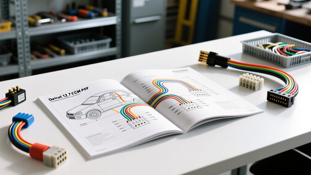
Decoding the Detroit 12.7 ECM Wiring Diagram PDF Landscape
When servicing the legendary Detroit Diesel 12.7L Series 60 engine, finding an accurate Detroit 12.7 ECM wiring diagram PDF is only the first step in a successful repair or swap. The 12.7L (775 CID) inline-six relies heavily on its Electronic Control Module (ECM) to manage fuel injection timing, boost pressure, and emissions. However, the transition between the DDEC III and DDEC IV generations introduced massive architectural shifts in how the ECM communicates with the chassis and diagnostic tools.
As an automotive electrical specialist, I frequently see fleet managers and owner-operators purchase the wrong replacement harness or misinterpret a generic schematic, leading to fried ECMs, no-start conditions, or ghost codes. This product comparison and selection guide will help you navigate the differences between DDEC generations, compare OEM versus aftermarket harness options, and provide the exact AWG and pinout specifications you need to wire your 12.7L Series 60 correctly.
DDEC III vs. DDEC IV: Selecting the Correct Schematic
Before you download any schematic, you must identify your ECM generation. The physical connectors may look similar, but the internal pin assignments and data protocols are vastly different. Using a DDEC III diagram on a DDEC IV harness will result in immediate communication failures and potential short circuits on the data bus.
| Feature | DDEC III (Approx. 1997-2000) | DDEC IV (Approx. 2000-2003) |
|---|---|---|
| Primary Data Link | SAE J1708 / J1587 | SAE J1939 (CAN Bus) & J1708 |
| Main Power Connector | 6-Pin (Metri-Pack 280) | 6-Pin (Metri-Pack 280) |
| Main Data Connector | 30-Pin AMP | 30-Pin AMP (with CAN pins) |
| Sensor Voltage Ref | 5V / 12V mixed | Strict 5V regulated |
| Diagram Focus | Analog sensor routing | CAN bus termination & shielding |
The most critical difference lies in the data link. DDEC III relies almost exclusively on the SAE J1708 Standard for diagnostic communication. DDEC IV introduced the SAE J1939 CAN Bus Protocol, requiring twisted-pair shielded cabling for the CAN High and CAN Low circuits to prevent electromagnetic interference (EMI) from the 12.7L's high-output alternator and injector solenoids.
Product Comparison: OEM vs. Aftermarket Engine Harnesses
When your existing harness shows signs of chafing, heat degradation, or corroded pins, you must select a replacement. The market offers three primary tiers of wiring harnesses for the 12.7L Series 60. Here is how they compare in terms of material quality, longevity, and application.
1. OEM Delphi / Continental Replacement Harnesses
Best For: Strict fleet compliance, warranty preservation, and exact factory routing.
Construction: Uses proprietary molded looms and factory-spec TXL (Thermoplastic Cross-Linked) wire. The connectors feature exact OEM weather seals and terminal tension.
Pros: Plug-and-play installation; guaranteed pinout accuracy; matches factory Detroit Diesel Official Service Manuals.
Cons: Highest price point (often $800-$1,200+); long lead times through dealership networks; TXL insulation is good but slightly less heat-resistant than premium GXL.
2. Premium Heavy-Duty Fleet Spec (Aftermarket)
Best For: Severe-duty applications, custom chassis swaps, and high-heat environments.
Construction: Upgrades to GXL (General Cross-Linked) wire insulation, which offers a thinner wall thickness for tighter bends and a higher continuous temperature rating (125°C vs 105°C). Often includes integrated Deutsch DT pigtails for sensors instead of molded OEM plugs, allowing for easier field repairs.
Pros: Superior abrasion and heat resistance; modular repairability; often includes upgraded braided shielding for J1939 CAN bus circuits.
Cons: Requires minor custom routing; slightly higher cost than budget options.
3. Universal / Budget Aftermarket Harnesses
Best For: Temporary fixes, low-budget restorations, or non-critical stationary applications.
Construction: Standard PVC (Polyvinyl Chloride) insulation with generic stamped brass terminals.
Pros: Inexpensive ($150-$250); widely available at local auto parts stores.
Cons: PVC insulation becomes brittle and cracks when exposed to the 12.7L exhaust manifold heat; generic terminals lose tension over time, causing intermittent voltage drops that trigger false ECM sensor codes.
Critical Pinouts: 6-Pin Power and 30-Pin Data Connectors
Whether you are building a custom harness or verifying an existing one against your Detroit 12.7 ECM wiring diagram PDF, you must adhere to strict AWG (American Wire Gauge) sizing. The 12.7L ECM draws significant current during the initial injector solenoid firing sequence. Undersized power wires will cause voltage sag, leading to ECM resets while cranking.
6-Pin Power Connector (Metri-Pack 280 Series)
| Pin | Wire Color | AWG Size | Function / Description |
|---|---|---|---|
| A | Red | 10 AWG | Unswitched Battery (+) - Main ECM Memory |
| B | Black | 10 AWG | Battery Ground (-) - Primary Chassis Ground |
| C | White | 14 AWG | Switched Ignition (+) - Key ON Wake-Up |
| D | Red | 10 AWG | Unswitched Battery (+) - Injector Driver Power |
| E | Black | 10 AWG | Battery Ground (-) - Injector Return Path |
| F | Blue | 18 AWG | Diagnostic Request / Sleep Mode Signal |
30-Pin Data Connector (Selected Critical Pins)
The 30-pin connector handles sensor inputs, chassis outputs, and data links. Below are the most frequently miswired pins during DDEC III to DDEC IV swaps.
- Pin 1 (Green, 18 AWG): J1708 Data (+). Used on both DDEC III and IV for legacy diagnostic tools.
- Pin 2 (Yellow, 18 AWG): J1708 Data (-).
- Pin 12 (Green/White, 18 AWG): J1939 CAN High. (DDEC IV Only - Must be twisted with Pin 13).
- Pin 13 (Yellow/Black, 18 AWG): J1939 CAN Low. (DDEC IV Only - Requires 120-ohm termination resistor at the bus ends).
- Pin 22 (Purple, 16 AWG): VSS (Vehicle Speed Sensor) Input. Highly sensitive to EMI; must be shielded.
Wire Insulation and Crimping Selection Guide
When repairing a harness based on your schematic, the wire type and crimping method are just as important as the routing. The Detroit 12.7L engine bay generates extreme ambient heat, particularly near the exhaust manifold and turbocharger.
- Insulation: Always select GXL (General Cross-Linked) or TXL wire. Never use standard PVC primary wire, as it will melt and short against the engine block. GXL is rated for continuous use at 125°C (257°F).
- Crimping: Use open-barrel U-crimp terminals for Metri-Pack connectors. Avoid closed-barrel ring terminals spliced into OEM harnesses; instead, use adhesive-lined marine-grade heat shrink (3:1 shrink ratio) to prevent moisture wicking into the copper strands.
- Shielding: For DDEC IV CAN bus circuits (Pins 12 and 13), use a braided copper shield grounded at one end only (typically the ECM side) to prevent ground loops.
Real-World Troubleshooting: When the Diagram Doesn't Match the Truck
Fleet trucks often undergo "chassis swaps" or ECM replacements where the physical harness doesn't match the factory Detroit 12.7 ECM wiring diagram PDF. Use this decision tree to diagnose mismatched wiring:
Symptom: ECM Powers Up, But No Communication with Diagnostic Laptop
- Check Pin F (6-Pin): Verify 12V on the Blue wire when the diagnostic tool requests a wake-up. If missing, the tool cannot pull the ECM out of sleep mode.
- Verify Protocol Match: If using a J1939 adapter on a DDEC III truck, it will fail. DDEC III requires a J1708 (6-pin or 9-pin Deutsch) adapter.
- Inspect CAN Termination: On DDEC IV, measure resistance between Pin 12 and Pin 13 at the diagnostic port. You should read exactly 60 ohms (two 120-ohm resistors in parallel). If you read 120 ohms, one termination resistor is missing or broken.
Symptom: Intermittent Injector Misfire Codes (e.g., Code 21, 22, 23)
- Load Test Power Pins: Do not just check for 12V with a multimeter. Use a headlight bulb or carbon pile tester to load-test Pins A and D. A corroded bulkhead connector will show 12V with no load, but drop to 8V under the 15-amp draw of the injector solenoids.
- Check Ground Pins B & E: Voltage drop across the ground wires should not exceed 0.1V during cranking. If it does, the 10 AWG ground wires are undersized or corroded.
Conclusion
Servicing the Detroit Diesel 12.7L Series 60 requires more than just glancing at a generic schematic. By understanding the architectural differences between DDEC III and DDEC IV, selecting the correct GXL-insulated harness tier for your specific duty cycle, and strictly adhering to the 10 AWG power and 18 AWG twisted-pair data specifications, you can eliminate electrical gremlins and keep your heavy-duty rig on the road. Always cross-reference your physical harness pinouts with the official Detroit Diesel Official Service Manuals before applying power to a newly installed ECM.