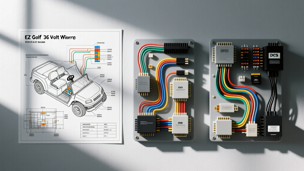
Selecting the Correct EZ Go Golf Cart 36 Volt Wiring Diagrams
When diagnosing, repairing, or upgrading an E-Z-GO TXT fleet or personal vehicle, identifying the exact drive system is the critical first step. The search for 'ez go golf cart 36 volt wiring diagrams' covers a massive span of production years and three entirely distinct electrical architectures. Using a DCS (Drive Control System) schematic on a PDS (Precision Drive System) cart will result in immediate controller failure, blown solenoids, or severe electrical fires. This comparison and selection guide will help you identify your specific 36V architecture, select the correct wiring diagram, and understand the precise AWG, pinout, and component specifications required for your project.
Identifying Your 36V Architecture: Series vs. DCS vs. PDS
Before pulling any wiring schematics, you must visually confirm which of the three primary 36V E-Z-GO TXT systems your cart utilizes. The 36V pack itself is universal (six 6V GC2 deep-cycle batteries wired in series), but the control logic differs drastically.
1. The Series (Resistor) System (Pre-1994)
The Series system is entirely analog. It uses a mechanical 5-speed resistor board to control acceleration. Visual Cue: The cart has a mechanical Forward/Reverse (F&R) lever on the dash or under the seat, and the accelerator pedal physically moves a wiper arm across a ceramic resistor coil. There is no solid-state computer controller. Wiring diagrams for this system focus on heavy-gauge power routing and mechanical switch alignments rather than data signals.
2. DCS (Drive Control System) (1994-1995)
DCS introduced the first solid-state motor controller to the TXT line. Visual Cue: The cart still uses a mechanical F&R lever, but the resistor board is gone. Instead, an inductive throttle sensor (ITS) is located in the driver-side throttle box. The controller features a 5-pin or 7-pin diagnostic connector. DCS diagrams require careful attention to the separation of high-current motor leads and low-voltage logic wires.
3. PDS (Precision Drive System) (1996-2011)
PDS is the most common and advanced 36V architecture. Visual Cue: The cart features a dashboard-mounted rocker switch for Forward/Neutral/Reverse, a 'Run/Tow' maintenance switch located under the passenger seat, and a 13-pin main harness connector at the controller. PDS diagrams are complex, integrating regenerative braking logic, speed limiting, and multi-step tow modes.
Main Power Cable Routing and AWG Specifications
Regardless of the control system, the main battery pack wiring must adhere to strict AWG (American Wire Gauge) standards to prevent voltage drop and thermal runaway. According to the SAE J1128 Low Tension Primary Cable Standard, DC high-current automotive applications require pure stranded copper with high-temperature insulation.
| System Type | Recommended Cable AWG | Peak Amperage Draw | Terminal Lug Size | Torque Specification |
|---|---|---|---|---|
| Series (Resistor) | 4 AWG (Minimum) | 250A - 300A | 3/8' Ring (3/8'-16 Bolt) | 14-16 ft-lbs |
| DCS (Early Solid State) | 4 AWG or 2 AWG | 300A - 350A | 3/8' Ring (3/8'-16 Bolt) | 14-16 ft-lbs |
| PDS (Precision Drive) | 2 AWG (Highly Recommended) | 350A - 400A+ | 3/8' Ring (3/8'-16 Bolt) | 14-16 ft-lbs |
Expert Tip: Never use Copper Clad Aluminum (CCA) wire for golf cart main power runs. CCA has higher resistance and will generate excessive heat at the battery terminals and solenoid lugs under heavy load, leading to melted insulation and voltage starvation at the controller.
Solenoid and Precharge Circuit Selection
The heavy-duty solenoid acts as the main contactor, bridging the 36V battery pack to the controller's B+ terminal. When selecting a wiring diagram for replacement or upgrade, the precharge circuit is the most frequently omitted—and most critical—component.
The Precharge Resistor
Inside the PDS and DCS controllers is a massive bank of capacitors. When the solenoid engages, these capacitors act as a dead short, pulling thousands of amps for a microsecond. Without a precharge resistor, this inrush current will pit and eventually weld the solenoid's heavy-duty contacts shut, causing a 'runaway cart' scenario. Your wiring diagram must include a 250-ohm, 10-watt ceramic resistor wired in parallel across the solenoid's large load terminals. This resistor gently charges the controller capacitors milliseconds before the main contacts close.
The Flyback Diode
The solenoid coil is a large inductor. When the microswitch breaks the 36V coil circuit, the collapsing magnetic field generates a high-voltage spike (inductive kickback) that can fry the controller's internal logic or melt the F&R microswitches. A 1N4004 or equivalent flyback diode must be wired across the small coil terminals, with the diode stripe pointing toward the positive (key switch) side.
PDS 13-Pin Controller Pinout Configuration
For technicians working on 1996-2011 models, the PDS 13-pin connector is the nerve center of the vehicle. When referencing ez go golf cart 36 volt wiring diagrams for PDS models, verify your harness against this standard OEM pinout:
- Pin 1 (Red): B+ (36V Main Power from Solenoid)
- Pin 2 (Black): B- (Main Ground to Battery Pack Negative)
- Pin 3 (Yellow): Motor Field 1
- Pin 4 (Green): Motor Field 2
- Pin 5 (Blue): Motor Armature
- Pin 6 (White): Throttle Signal (0.8V - 3.2V from ITS)
- Pin 7 (Orange): 15V Reference (Output to ITS)
- Pin 8 (Black/White): Sensor Ground (Return for ITS)
- Pin 9 (Gray): F&R Switch - Forward Input
- Pin 10 (Violet): F&R Switch - Reverse Input
- Pin 11 (Brown): Brake/Hold Microswitch Input
- Pin 12 (Red/White): Key Switch 36V Input
- Pin 13 (Empty/Shield): Reserved / Harness Shield Drain
Note: Always use a digital multimeter to back-probe these pins. Piercing wire insulation with test probes introduces moisture and causes green corrosion inside the harness loom.
Inductive Throttle Sensor (ITS) vs. Potentiometer Wiring
A common error when using generic wiring diagrams is confusing the throttle input. Older Series carts used a 0-5k ohm potentiometer. DCS and PDS systems use an Inductive Throttle Sensor (ITS). The ITS does not use resistance; it relies on a variable inductance circuit powered by the controller's 15V reference (Pin 7). If you are swapping a motor or controller, ensure your diagram reflects the 3-wire ITS setup (15V, Ground, Signal) rather than the 2-wire potentiometer setup. An incorrect ITS alignment will result in a high-pedal fault, where the controller refuses to engage the solenoid because it detects the throttle is already depressed upon key-up.
Upgrading from Series to PDS: Harness Requirements
Many fleet owners and DIYers use 36V wiring diagrams to upgrade an old Series cart to a modern PDS system for regenerative braking and smoother torque curves. This is not a simple plug-and-play swap. You must replace the entire main wiring harness. The Series cart relies on the F&R switch to physically reverse the motor field polarity using heavy 4 AWG cables. The PDS system keeps the motor cables static and uses the controller's logic board and low-voltage microswitches (Pins 9 and 10) to reverse the field electronically. Attempting to adapt a Series harness to a PDS controller will result in catastrophic short circuits.
Common 36V Wiring Failures and Troubleshooting
Use this diagnostic tree when your 36V TXT cart fails to operate:
- Solenoid Does Not Click: Check the Run/Tow switch (PDS only). If in 'Tow', the controller is disabled. Next, check the F&R microswitches. The microswitch must audibly click before the mechanical cam reaches the end of its travel. If the switch clicks too late, the cart will not receive the directional logic signal.
- Solenoid Clicks, But Cart Does Not Move: The logic circuit is working, but the high-current circuit is failing. Check for voltage drop across the solenoid load terminals while the pedal is depressed. If you read 36V on the battery side and 0V on the controller side, the solenoid contacts are burnt, or the precharge resistor is blown (preventing the capacitors from charging, which keeps the controller from opening the internal MOSFETs).
- Cart Moves, But Loses Power Under Load: Inspect the battery interconnect cables. A loose 5/16' battery terminal bolt will arc under load, creating a massive voltage drop. Torque all battery connections to 110-120 in-lbs and clean terminals with a baking soda solution and a brass wire brush.
Authoritative References
For further technical validation, consult the following industry standards and manufacturer resources:
- SAE J1128 Low Tension Primary Cable Standard - Guidelines for AWG selection and insulation temperature ratings in DC automotive environments.
- NFPA 70 National Electrical Code (NEC) - Article 690 and general DC wiring safety clearances for battery compartments.
- E-Z-GO Official Parts and Service Documentation - OEM exploded views, harness part numbers, and factory torque specifications for TXT fleet and personal vehicles.