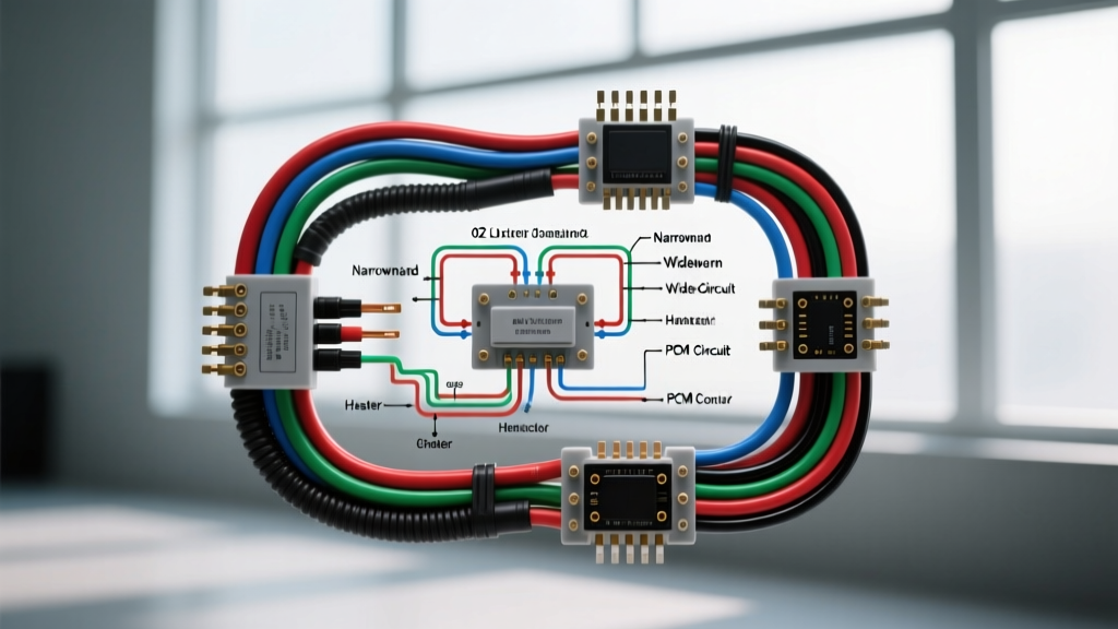
Decoding the 02 Sensor Wiring Diagram: An Advanced Technical Deep Dive
When technicians and performance tuners search for a 02 sensor wiring diagram, they are referencing the Oxygen (O2) sensor circuit—a critical feedback loop for closed-loop fuel control and emissions compliance. While "02" is a common typographical variant of "O2" in automotive forums and legacy search queries, the underlying electrochemical principles and wiring topologies remain identical. Understanding the architecture of these circuits requires moving beyond basic multimeter testing and delving into pulse-width modulation (PWM) heater controls, signal shielding, and wideband pump cell dynamics.
This advanced guide dissects the 02 sensor wiring diagram for the ubiquitous GM LS platform (Gen III/IV 5.3L and 6.0L engines), contrasting the factory narrowband zirconia sensors with aftermarket Bosch LSU 4.9 wideband integrations. We will cover specific OEM wire color codes, AWG requirements, PCM pinouts, and real-world failure modes that plague high-mileage and high-performance harnesses.
Narrowband Zirconia 02 Sensor Wiring Diagram Architecture
The factory GM LS narrowband O2 sensor operates on a zirconia dioxide principle, generating a voltage between 0.1V (lean) and 0.9V (rich) based on the oxygen differential between the exhaust gas and ambient atmosphere. The wiring harness for this system utilizes a 4-wire configuration: two wires for the internal ceramic heater element, and two wires for the electrochemical signal and reference ground.
Unlike older single-wire sensors that relied on the engine block for grounding, modern 02 sensor wiring diagrams utilize a dedicated, isolated reference ground (Low Signal) routed directly back to the Powertrain Control Module (PCM). This prevents voltage offsets caused by poor engine-to-chassis grounds, which can skew fuel trims by up to 15%.
GM LS Gen III/IV Narrowband Pinout and Wire Specifications
The following table details the OEM wiring specifications for a standard GM LS 5.3L (e.g., LM7/L59) Bank 1 and Bank 2 Sensor 1 (pre-cat) circuits. Data is cross-referenced with Helm Incorporated OEM Service Manuals.
| Circuit Function | Bank 1 Sensor 1 Wire Color | Bank 2 Sensor 1 Wire Color | AWG | PCM Connector / Pin |
|---|---|---|---|---|
| Signal (High) | Purple | Dark Green | 20 AWG | C1 / Pin 25 (B1), C1 / Pin 24 (B2) |
| Low Signal (Reference Gnd) | Tan | Tan/White | 20 AWG | C1 / Pin 8 (B1), C1 / Pin 7 (B2) |
| Heater 12V Feed | Pink | Pink | 16 AWG | Fuse Block (IGN Fused) |
| Heater Control (PWM Gnd) | Black/White | Dark Green/White | 16 AWG | C2 / Pin 12 (B1), C2 / Pin 11 (B2) |
Wideband Integration: The Bosch LSU 4.9 02 Sensor Wiring Diagram
For forced-induction LS builds or precise dyno tuning, the narrowband sensor's non-linear response curve is insufficient. Tuners upgrade to a wideband controller utilizing the Bosch LSU 4.9 sensor. The 02 sensor wiring diagram for a wideband system is exponentially more complex, utilizing a 5-wire (6-pin connector) configuration to manage a pump cell, a reference cell, and a calibration resistor.
According to Bosch Motorsport LSU 4.9 Technical Documentation, the wideband sensor does not output a simple voltage. Instead, the controller alters the current to the pump cell to maintain the reference cell at a constant lambda of 1.0 (450mV). The current required to maintain this balance is directly proportional to the oxygen content in the exhaust.
LSU 4.9 Sensor Pigtail Pinout Chart
| Connector Pin | Wire Color | Function | Technical Notes |
|---|---|---|---|
| Pin 1 | White | Calibration Resistor | Do not modify or extend. Contains laser-trimmed resistor. |
| Pin 2 | Grey | Calibration Resistor | Measures typically between 60 and 120 ohms. |
| Pin 3 | Red | Pump Cell (+) | Carries the pump current (Ip) proportional to AFR. |
| Pin 4 | Yellow | Pump Cell (-) | Reference ground for pump circuit. |
| Pin 5 | Black | Heater (+) | Requires 12V-14V. Draws up to 2.5A at startup. |
| Pin 6 | Black | Heater (-) | Switched ground via controller MOSFET. |
Heater Circuit Diagnostics and AWG Specifications
The most frequently misunderstood aspect of any 02 sensor wiring diagram is the heater circuit. The internal ceramic heater must reach 600°C (1112°F) for the zirconia element to become conductive. On a cold start, the PCM applies a high-duty-cycle Pulse Width Modulation (PWM) signal to the heater ground circuit to rapidly heat the element without thermal shocking the ceramic.
AWG and Current Draw: The heater element can draw between 2.0A and 4.0A during the initial 30 seconds of operation. Using standard 20 AWG signal wire for the heater circuit will result in severe voltage drop, harness melting, and eventual PCM driver failure. The OEM 02 sensor wiring diagram mandates 16 AWG stranded copper for the Pink (12V) and Black/White (PWM Ground) circuits to handle the thermal load and current spikes safely.
Diagnostic Step: Connect an oscilloscope to the heater control wire (e.g., Black/White). Upon key-on/engine-off (KOEO), you should see a 12V square wave. As the exhaust heats up, the PCM will reduce the duty cycle to maintain the target 600°C. If the scope shows a flat 12V line with no PWM switching, the PCM internal driver has likely failed due to a shorted heater element inside the sensor.
Signal Shielding and EMI Mitigation in 02 Sensor Harnesses
The GM LS platform utilizes a coil-near-plug (CNP) ignition system, which generates massive electromagnetic interference (EMI). The 02 sensor signal wire operates in the millivolt range (narrowband) or milliamp range (wideband), making it highly susceptible to capacitive and inductive coupling from the ignition harness.
In performance applications where the OEM harness is replaced or extended, the 02 sensor wiring diagram must incorporate a drain wire and foil shield.
- Shielding Material: Use aluminum foil tape or braided copper shielding wrapped around the signal and reference ground wires.
- Drain Wire Routing: The bare copper drain wire must be grounded at the PCM connector end ONLY. Grounding the shield at both the sensor and the PCM creates a ground loop, which will inject alternator whine and ignition noise directly into the O2 signal trace.
- Separation: Maintain a minimum 2-inch physical separation between the O2 signal wires and the fuel injector or ignition coil power feeds.
Advanced Oscilloscope Diagnostics for 02 Sensor Circuits
Relying on a digital multimeter (DMM) for O2 sensor diagnostics is an outdated practice. The sampling rate of a standard DMM is too slow to capture the rapid cross-counts of a healthy sensor or the high-frequency noise of a failing one. As noted in SAE Technical Paper 2004-01-0982 on Oxygen Sensor Diagnostics, waveform analysis is the only definitive method for verifying sensor health and harness integrity.
Waveform Analysis Checklist
- Bias Voltage Check: With the sensor unplugged and KOEO, probe the PCM signal wire (e.g., Purple). The PCM should output a bias voltage of exactly 450mV (0.45V). If it reads 0V or 12V, the PCM internal pull-up/pull-down resistor network is compromised.
- Cross-Count Frequency: At operating temperature and closed-loop idle, the narrowband signal should oscillate between 100mV and 800mV. A healthy LS engine will show 1 to 5 cross-counts per second. A sluggish waveform that peaks at 600mV indicates a contaminated sensor (silicone or coolant poisoning).
- Reference Ground Integrity: Probe the Low Signal wire (Tan) simultaneously with the Signal wire. The Low Signal trace should remain perfectly flat at 0.00V. If the reference ground trace shows AC noise or lifts above 50mV during cranking, the dedicated PCM ground circuit has excessive resistance, artificially skewing the fuel trims rich.
Common Failure Modes and Harness Degradation
When troubleshooting a 02 sensor wiring diagram, technicians must look beyond the sensor itself. The harsh environment of the exhaust tunnel introduces specific failure modes:
- Capillary Action Ingress: If the sensor harness is submerged in water (e.g., deep puddles), moisture can wick through the wire strands via capillary action, eventually reaching the PCM connector and causing green corrosion on the C1/C2 pins. Always use dielectric grease and drip loops when routing harnesses.
- Calibration Resistor Drift: On wideband setups, if the LSU 4.9 pigtail is cut and soldered incorrectly, the heat from the soldering iron can alter the resistance of the internal calibration resistor (Pins 1 and 2). This will cause a permanent AFR offset. Never solder within 4 inches of the wideband sensor connector.
- PWM Transistor Thermal Fatigue: Repeatedly using a cheap, high-resistance aftermarket O2 sensor forces the PCM's heater control transistor to work harder to maintain the target temperature. Over time, this thermal fatigue cracks the silicon die inside the PCM, resulting in a permanent P0030 or P0036 heater circuit DTC.
Mastering the 02 sensor wiring diagram requires a holistic approach that respects OEM wire gauges, understands the electrochemical feedback loops, and utilizes advanced oscilloscope diagnostics to verify the integrity of every millivolt and milliamp in the circuit.