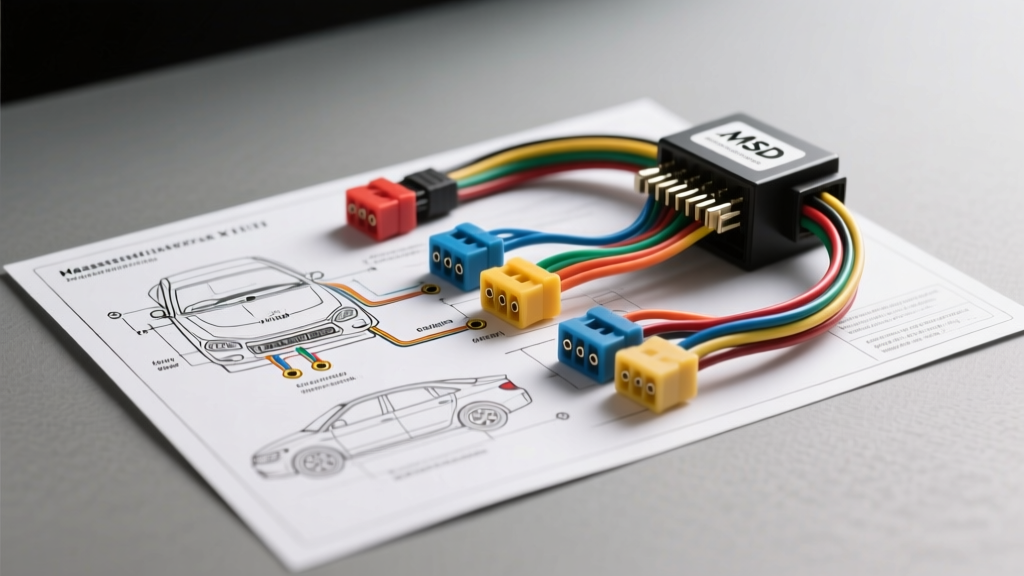
Decoding the MSD Ignition Wiring Diagram for Capacitive Discharge Systems
Upgrading to a capacitive discharge ignition system, such as the legendary MSD 6AL (PN 6425) or the standard MSD 6, fundamentally changes how your engine manages spark energy. However, interpreting an MSD ignition wiring diagram and executing the physical installation requires strict adherence to electrical best practices. Unlike factory inductive systems that rely on a simple 12V switched feed and a basic ground, MSD units demand high-amperage power delivery, precise trigger signal isolation, and dedicated coil routing. When a no-spark condition or erratic tachometer behavior occurs, guessing is not an option. This guide provides a systematic, step-by-step troubleshooting flow to isolate faults using your multimeter and the factory wiring schematic.
Phase 1: Heavy Gauge Power and Ground Verification
The most common cause of MSD failure under load (such as high-RPM spark blowout or complete unit shutdown) is inadequate current delivery on the heavy gauge circuits. The MSD 6-series draws significant amperage during high-RPM operation, and relying on factory bulkhead connectors or undersized wiring will cause severe voltage drop.
Step 1: The Heavy Red Wire (12V+ Battery Feed)
The heavy red wire must be connected directly to the positive terminal of the battery or a high-amperage distribution bus bar. It must never be spliced into a factory ignition switch feed. According to SAE J1141 standards for automotive electrical systems, high-draw aftermarket components require dedicated circuits. Verify that you are using a minimum of 8 AWG (preferably 6 AWG for runs over 6 feet) stranded copper wire. Set your multimeter to DC Volts. With the engine cranking, measure the voltage between the heavy red wire at the MSD connector and the battery negative terminal. If the reading drops below 10.5V during cranking, you have a high-resistance fault in the power feed.
Step 2: The Heavy Black Wire (Main System Ground)
Capacitive discharge units dump massive amounts of energy into the coil primary winding, and that energy must return to the source instantly. The heavy black wire must be grounded directly to the engine block or cylinder head using a minimum 8 AWG wire. Paint, powder coating, and rust act as insulators. As detailed in the Holley/MSD Grounding Tech Article, you must sand down to bare metal, use a star washer to bite into the surface, and apply dielectric grease over the finished connection to prevent galvanic corrosion. Perform a voltage drop test across the ground wire while cranking; any reading over 0.1V indicates a failing ground path.
Phase 2: Trigger Circuit Isolation (White, Violet, and Green Wires)
Once main power and ground are verified, the next step in the MSD ignition wiring diagram flow is isolating the trigger signal. The MSD unit needs to know exactly when to fire the coil, and it accepts multiple trigger sources via the light-gauge harness.
Step 3: White Wire (Points / Amplifier Trigger)
If you are using a factory HEI module, an aftermarket points distributor, or an EFI ECU tach output to trigger the MSD, you will use the white wire. The white wire requires a 12V switched signal to activate. Crucial troubleshooting note: The white wire triggers on the rising edge of the voltage signal. If your EFI ECU provides a 5V square wave or a ground-switched (pull-down) signal, the white wire will not trigger the box. You must use an MSD Two-Wire Trigger Converter (PN 8874) to adapt a 5V or ground-switched signal to the 12V rising-edge requirement. Test the white wire with a logic probe or multimeter; you should see 0V at rest, and a clean jump to 12V when the trigger event occurs.
Step 4: Violet and Green Wires (Magnetic Pickup Trigger)
If you are running a dedicated magnetic pickup distributor (like an MSD Pro-Billet), you will use the violet and green wires. These wires carry a low-voltage AC sine wave generated by the reluctor wheel passing the pickup coil. Never connect the violet/green wires to a 12V source, or you will instantly destroy the internal opto-isolators. To test this circuit, set your multimeter to AC Volts. Crank the engine; you should see between 1.5V and 3.0V AC. If the reading is 0V, check the air gap between the reluctor and the pickup (spec is typically 0.005 to 0.010 inches) and verify the harness for broken shielded wiring.
Phase 3: Coil Output and Tachometer Signal Diagnosis
Step 5: Orange and Black Wires (Coil Connection)
The orange wire connects to the positive terminal of the ignition coil, and the black wire connects to the negative terminal. Do not use a standard OEM inductive coil; MSD boxes require a low-resistance, high-turn-ratio coil (such as the MSD Blaster 2, PN 8202) with a primary resistance between 0.4 and 0.8 ohms. If your coil primary resistance is too high (above 1.0 ohm), the MSD box will overheat and shut down to protect its internal IGBTs. Disconnect the coil and measure the primary resistance with an ohmmeter to verify compatibility.
Step 6: Green Wire (Tachometer Output)
The green wire provides a 12V square wave tachometer signal. A common failure mode is a bouncing or dead tachometer needle after installation. This occurs because older OEM tachometers were designed to read the dwell-time voltage spikes of a points system, not the 12V square wave of an MSD. If your tachometer behaves erratically, install an MSD Tach Adapter (PN 8910) inline with the green wire to filter and reshape the signal for your specific gauge.
MSD 6-Series Master Wire Color & Pinout Table
Reference this table against your physical harness to ensure no cross-wiring has occurred during installation or previous troubleshooting attempts.
| Wire Color | Function | AWG Size | Connection Destination | Signal Type |
|---|---|---|---|---|
| Heavy Red | Main Power | 8 AWG | Battery Positive (+) | 12V DC Constant |
| Heavy Black | Main Ground | 8 AWG | Engine Block / Cylinder Head | Ground Return |
| Red | Switched Ignition | 18 AWG | 12V Ignition Switch Source | 12V DC Switched |
| White | Points / Amp Trigger | 18 AWG | Points, HEI, or ECU Tach Out | 12V Rising Edge |
| Violet | Magnetic Pickup (+) | 18 AWG | Distributor Pickup (+) | AC Sine Wave |
| Green (Thin) | Magnetic Pickup (-) | 18 AWG | Distributor Pickup (-) | AC Sine Wave |
| Orange | Coil Positive | 18 AWG | Ignition Coil (+) | High Voltage Pulse |
| Black (Thin) | Coil Negative | 18 AWG | Ignition Coil (-) | High Voltage Pulse |
| Green (Thick) | Tachometer Output | 18 AWG | Tachometer Input | 12V Square Wave |
Step-by-Step No-Spark Decision Tree
Use this diagnostic flow when the engine cranks but fails to fire. Follow the steps sequentially; do not skip ahead.
- Symptom: Engine cranks, zero spark, no tach movement.
- Check 1: Verify 12V at the small Red wire during cranking. If 0V, repair ignition switch feed.
- Check 2: If 12V is present, verify the trigger source. If using the White wire, ensure it sees 12V during cranking. If using Violet/Green, check for AC voltage.
- Check 3: If triggers are good, test coil primary resistance. Replace coil if out of spec.
- Symptom: Engine fires but dies immediately when key returns from 'Start' to 'Run'.
- Cause: The small Red wire (switched 12V) is wired to the starter solenoid 'I' terminal instead of a true ignition-run source. The 'I' terminal only provides power during cranking.
- Fix: Reroute the small Red wire to a fuse box terminal that is hot only in the 'Run' and 'Start' positions.
- Symptom: Engine runs, but backfires through carburetor at high RPM.
- Cause: Trigger signal loss or severe voltage drop on the heavy Red wire causing the MSD to misfire or drop sparks.
- Fix: Perform a voltage drop test on the heavy Red wire at 3000 RPM. Upgrade to 6 AWG wire and add a 40A relay if the battery is trunk-mounted.
- Symptom: Tachometer pegs to max RPM or reads zero.
- Cause: Incompatible tachometer impedance or missing tach adapter.
- Fix: Install MSD PN 8910 Tach Adapter. Verify the green wire is not shorted to ground.
Final Verification and SAE Compliance
After resolving the fault, secure all wiring using SAE-compliant methods. Avoid using standard vinyl electrical tape in the engine bay, as heat will melt the adhesive and cause harness unraveling. Instead, use Tesa 51036 PET cloth tape or split-loom tubing secured with adhesive-lined heat shrink. Ensure all MSD ignition wiring diagram connections are protected from exhaust heat and moving steering components. By treating the MSD harness as a high-current data and power network rather than simple accessory wiring, you guarantee consistent, high-energy spark delivery across the entire RPM range.
For further reading on factory wiring integration and pinout verification, always consult the MSD 6AL Official Instructions and your vehicle's specific factory service manual before cutting or splicing any OEM harnesses.