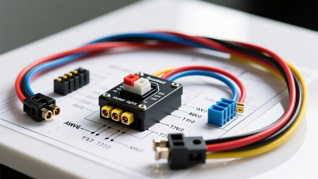
Introduction to Off-Road Rocker Switch Panels
Upgrading your truck, Jeep, or SUV with auxiliary LED light bars, winches, or onboard air compressors requires a reliable command center. The automotive rocker switch panel is the nerve center for these modifications. However, the most common mistake beginners make is running high-amperage loads directly through the switch contacts. This inevitably leads to melted switch housings, voltage drop, and potential electrical fires. To properly wire a rocker switch panel, you must use a relay-based circuit. This guide provides a comprehensive, beginner-friendly wiring diagram and technical breakdown on how to wire a rocker switch panel safely, utilizing industry-standard components and SAE specifications.
The Anatomy of a Standard 5-Pin Automotive Rocker Switch
Most off-road switch panels (such as those modeled after Carling V-series or Nilight SPST designs) utilize a 5-pin configuration. While it is a Single Pole Single Throw (SPST) switch functionally, the extra pins are dedicated to the internal LED illumination circuit. Understanding these pins is critical before making any connections.
- Pin 1 (Ground): Completes the circuit for the switch's internal LED illumination. Connects to a clean chassis ground.
- Pin 2 (12V+ Input): The primary power source for both the switch illumination and the trigger signal to the relay. This should be sourced from an ignition-switched fuse block or a fused direct battery line, depending on whether you want the switches to have power only when the key is on.
- Pin 3 (Load Output): The switched 12V+ output. This pin sends a low-amperage trigger signal (typically under 1 Amp) to Pin 86 on your ISO Mini Relay.
- Pins 4 & 5: On standard 5-pin SPST switches, these are often left blank or reserved for a secondary illumination circuit (e.g., a dual-color LED that changes from blue to red when toggled). For basic auxiliary light wiring, these remain unused.
SAE J1128 Wire Insulation and the Danger of CCA
Before cutting any wire, you must select the correct cable type. Never use Copper-Clad Aluminum (CCA) wire for automotive applications. CCA has higher electrical resistance than pure copper, leading to severe voltage drop and excessive heat generation over long runs (like from the engine bay to the rear bumper). Always source pure copper wire that meets the SAE J1128 Standard. Specifically, look for GXL, TXL, or SXL insulation ratings. These cross-linked polyethylene insulations are rated for continuous operation at 125°C to 150°C, providing essential resistance against engine bay heat, abrasion, and automotive fluids.
Wire Gauge (AWG) and Fuse Sizing Chart
Proper wire sizing prevents voltage drop and ensures your auxiliary lights operate at peak brightness. The table below outlines the required American Wire Gauge (AWG) sizes for pure copper wire based on the amperage draw of your accessories and the corresponding inline fuse requirements. Reference Littelfuse automotive guidelines for precise derating in high-temperature engine bays.
| Circuit Segment | Max Amperage | Recommended AWG (Pure Copper) | Inline Fuse Size (ATO/Maxi) |
|---|---|---|---|
| Switch Trigger Circuit (Pins 1, 2, 3) | 5A | 18 AWG | 5A ATO (if not on fused block) |
| Relay to Load (Up to 120W LED Bar) | 10A | 14 AWG | 15A ATO / Maxi |
| Relay to Load (Up to 240W LED Bar) | 20A | 12 AWG | 20A or 25A ATO / Maxi |
| Relay to Load (Up to 360W+ / Winch Contactor) | 30A+ | 10 AWG or 8 AWG | 30A or 40A Maxi |
The Core Wiring Diagram: Switch to Relay to Load
To handle the heavy amperage of off-road lights, we use a standard Bosch-style ISO Mini 4-pin relay. The relay acts as a heavy-duty electromagnetic gate, allowing your delicate rocker switch to control high-current circuits safely. For a deeper understanding of relay mechanics and pin standardizations, consult the Hella/Bosch automotive relay technical documentation.
Relay Pinout Configuration
- Pin 85 (Ground): Connect to a clean, bare-metal chassis ground using a ring terminal and a star washer.
- Pin 86 (Trigger): Connects to Pin 3 (Load Output) on the rocker switch. This is the low-amp signal that energizes the relay coil.
- Pin 30 (Common / Power In): Connects directly to the positive battery terminal via a heavy-gauge wire (12 AWG or 10 AWG) and an inline Maxi fuse mounted within 18 inches of the battery.
- Pin 87 (Normally Open / Load Out): Connects to the positive input of your auxiliary LED light bar or accessory.
Step-by-Step Installation and Crimping Standards
- Disconnect the Battery: Always isolate the negative terminal before routing wires to prevent accidental short circuits against the chassis.
- Mount the Switch Panel: Cut the required bezel hole (typically 1.45" x 0.83" for standard panels). Ensure the panel is seated flush and the retaining clips snap securely into the dash or overhead console.
- Route the Harness: Feed the switch wiring through the firewall using an existing rubber grommet. Never drill through bare sheet metal without a rubber grommet, as chassis vibration will strip the wire insulation and cause a dead short.
- Crimp the Terminals: Use a ratcheting crimping tool for all connections. For the rocker switch pins, use 1/4" (6.3mm) fully insulated female spade disconnects. The ratcheting tool ensures the wire and terminal are cold-welded together, preventing resistance buildup. Soldering is generally discouraged in high-vibration automotive environments unless paired with an adhesive-lined heat shrink sleeve.
- Wire the Relay: Mount the ISO relay in a dry, protected area of the engine bay. Connect Pins 85, 86, 30, and 87 according to the diagram above. Use adhesive-lined marine-grade heat shrink on all butt splices to prevent moisture ingress and copper oxidation.
- Establish the Grounds: The number one cause of auxiliary light flickering is a poor ground. Sand away paint and clear coat down to bare steel. Secure the ground ring terminal with a stainless steel bolt, a star washer (to bite into the metal), and a nut. Apply a dab of dielectric grease over the terminal to prevent galvanic corrosion.
- Reconnect and Test: Reattach the battery negative terminal. Toggle the rocker switch. The switch LED should illuminate, the relay should emit an audible "click," and the auxiliary lights should power on at full brightness.
Real-World Troubleshooting & Failure Modes
Even with a perfect diagram, real-world variables can cause issues. Use this decision tree to diagnose common rocker switch panel failures.
| Symptom | Probable Cause | Diagnostic Fix |
|---|---|---|
| Switch gets physically hot to the touch | High-amperage load wired directly through the switch, bypassing the relay. | Immediately turn off. Rewire using an ISO relay so the switch only carries the <1A trigger load. |
| Switch LED lights up, but accessory does not turn on | Bad relay ground (Pin 85), blown main fuse (Pin 30), or faulty relay coil. | Check chassis ground for paint/corrosion. Test battery voltage at Pin 30. Swap relay with a known good unit. |
| Auxiliary lights flicker or appear dim | Voltage drop due to undersized AWG wire, excessive wire length, or loose crimps. | Measure voltage at the light terminals while on. If below 12.5V, upgrade to a thicker AWG wire or redo spade crimps. |
| Switch LED stays on even when toggled OFF | Backfeed from a secondary circuit or incorrect grounding of Pin 1. | Verify Pin 1 is grounded and Pin 2 is the 12V+ source. Do not reverse the input and ground on dual-LED switches. |
Final Expert Recommendations
Wiring a rocker switch panel is a foundational skill for any off-road enthusiast. By adhering to SAE wire standards, utilizing proper ratcheting crimp tools, and strictly employing relays for high-current loads, you ensure your vehicle's electrical system remains safe, reliable, and ready for the trail. Always double-check your fuse ratings against the specific amperage draw of your accessories, and protect every connection from the elements.