Introduction to Vehicle Intercom Fundamentals
Whether you are outfitting a Class A motorhome, a commercial transit van, or a custom luxury SUV, clear communication between the driver and rear passengers is a critical safety and convenience feature. However, the automotive electrical environment is notoriously hostile to low-voltage audio signals. When installing a cab-to-rear communication system, referencing a precise wiring diagram for intercom setups is critical to avoid alternator whine, voltage drop, and signal degradation. This beginner-friendly guide breaks down the fundamental circuit architecture, wire gauge requirements, and routing strategies necessary to achieve crystal-clear audio in a high-EMI (Electromagnetic Interference) vehicle environment.
Core Components of an RV Intercom Circuit
Before diving into the schematic, it is essential to understand the primary hardware nodes in a standard vehicle intercom loop. Unlike home audio systems, vehicle intercoms must withstand voltage spikes from the alternator and severe vibration. The core components include:
- Master Station (Cab): The primary control unit featuring the microphone, amplifier, and Push-To-Talk (PTT) momentary switch.
- Sub Station (Rear): The secondary speaker/microphone node, often passively amplified or equipped with a secondary pre-amp.
- Shielded Wiring Harness: The physical medium carrying both 12V DC power and low-voltage analog audio signals.
- Inline Fusing and Relays: Protection mechanisms to isolate the sensitive audio amplifier from the vehicle's primary 12V bus.
Decoding the Wiring Diagram for Intercom Pinouts
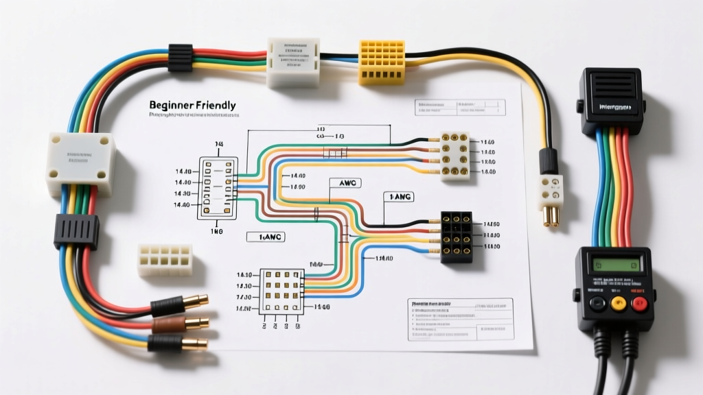
The most reliable wiring diagram for intercom applications in heavy-duty and RV use relies on a 6-pin sealed connector system, such as the industry-standard Deutsch DT series. This configuration separates the high-current power delivery from the sensitive audio signals, minimizing crosstalk. Below is the standard pinout configuration for the Master Station harness.
| Pin Number | Function | Wire Color Code | AWG Size & Type |
|---|---|---|---|
| 1 | +12V Switched Power (Ignition) | Red | 18 AWG (SAE J1128 Primary) |
| 2 | Chassis Ground (Star Point) | Black | 18 AWG (SAE J1128 Primary) |
| 3 | Audio Signal + (Non-Inverting) | White | 22 AWG (Shielded Twisted Pair) |
| 4 | Audio Signal - (Inverting) | Green | 22 AWG (Shielded Twisted Pair) |
| 5 | PTT Trigger / Remote Mute | Yellow | 20 AWG (Stranded Copper) |
| 6 | Shield Drain Wire | Bare Copper | 24 AWG (Tinned) |
According to SAE J1128 standards for low-tension primary cables, 18 AWG is sufficient for the power and ground pins, as most modern solid-state intercom amplifiers draw less than 1.5 amps under peak load. However, the audio pins (3 and 4) must utilize a Shielded Twisted Pair (STP) configuration. The twisting of the white and green wires cancels out induced magnetic fields, while the bare copper drain wire (Pin 6) provides a path for electrostatic interference to bleed off to the chassis ground.
Wire Routing and EMI Mitigation Strategies
The most common point of failure in DIY intercom installations is improper wire routing. A perfectly executed wiring diagram will fail if the harness is routed parallel to high-voltage ignition coils or the alternator output cable. To maintain signal integrity, adhere to the following routing fundamentals:
- Maintain Separation: Keep the intercom harness at least 6 inches away from the vehicle's primary power cables, ignition coil packs, and inverter AC lines. If crossing is unavoidable, cross at a strict 90-degree angle.
- Avoid the Dash Cluster: The area behind the instrument cluster is saturated with PWM (Pulse Width Modulation) signals from the ECU and dimmer switches. Route the intercom harness down the A-pillar and under the door sill plates instead of behind the radio bezel.
- Shield Grounding: The bare copper drain wire (Pin 6) must be grounded at one end only (typically the Master Station/amplifier end). Grounding the shield at both the cab and the rear of the RV creates a ground loop, which acts as an antenna for alternator whine.
Step-by-Step Termination and Connector Assembly
For automotive applications, standard plastic Molex connectors often fail due to vibration and moisture ingress. The TE Connectivity Deutsch DT Series is the preferred connector for RV intercoms due to its integrated silicone seals and secondary wedge-lock mechanism. When terminating the 18 AWG and 22 AWG wires into the solid stainless-steel contacts, follow this sequence:
- Strip exactly 5/32" (4mm) of insulation from the wire ends.
- Use a precision open-barrel crimp tool (such as the IWISS IWS-3220M) to crimp the contact. Do not use standard electrical pliers, as this will deform the contact and prevent it from seating in the housing.
- Insert the crimped contact into the rear of the DT housing until you hear a distinct "click."
- Insert the orange secondary wedge-lock to permanently secure the pins against vibration-induced back-out.
- Apply dielectric grease to the mating face of the connector before joining the master and sub-station harnesses to prevent moisture corrosion.
Troubleshooting Common Intercom Failures
Even with a flawless wiring diagram for intercom systems, real-world vehicle variables can introduce faults. Below is a diagnostic decision tree for the three most common RV intercom issues.
| Symptom | Probable Cause | Diagnostic Fix |
|---|---|---|
| High-pitched whine that changes pitch with engine RPM. | Alternator EMI induction or Ground Loop. | Verify the shield drain wire is grounded at ONE end only. Check for shared ground points with the vehicle's 12V cigarette lighter or inverter. |
| Audio is heavily distorted or clipping at high volumes. | Voltage drop on the +12V Switched line. | Measure voltage at Pin 1 while the engine is running. If below 13.2V, upgrade the power wire to 16 AWG or run a dedicated fused line to the battery. |
| Sub-station (rear) has no power or audio. | Broken pin or backed-out contact in the DT connector. | Remove the wedge-lock and inspect Pin 1 and Pin 2. Ensure the wire crimp was performed on the copper strands, not the insulation jacket. |
| PTT (Push-to-Talk) button fails to mute the rear speakers. | Trigger wire routed through a high-resistance path. | Check continuity on the Yellow wire (Pin 5). Ensure the PTT switch is grounding the circuit cleanly, not switching the +12V side. |
Implementing a Star Ground Topology
The RV Industry Association (RVIA) strongly recommends dedicated grounding strategies for sensitive aftermarket electronics. Never ground your intercom's audio shield or amplifier chassis to a seatbelt bolt or a shared interior lighting ground. These shared nodes are prone to transient voltage spikes when interior lights are switched or when seatbelt pretensioners cycle. Instead, establish a "Star Ground" topology. Run a dedicated 14 AWG ground wire from a clean, bare-metal point on the vehicle's main chassis frame directly to a centralized grounding busbar. Connect the Master Station ground (Pin 2) and the audio shield drain (Pin 6) exclusively to this isolated busbar. This ensures that high-current transients from other vehicle systems do not modulate the intercom's ground reference, resulting in a perfectly silent noise floor when the intercom is idle.
Summary
Designing and installing a vehicle communication system requires more than just connecting positive and negative wires. By adhering to a structured wiring diagram for intercom applications, utilizing SAE-rated shielded twisted pair cables, and executing proper Deutsch connector terminations, you can achieve professional-grade, noise-free audio. Always prioritize single-point shield grounding and strict physical separation from high-current ignition sources to ensure your cab-to-rear intercom performs flawlessly on the road.