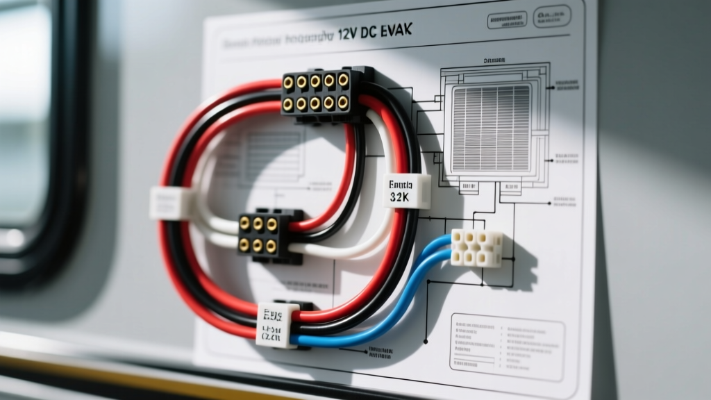
Introduction: Smart Climate Control in 12V Vehicle Systems
Upgrading a Class B camper van or Class A motorhome with smart home technology is a popular van-life and RV modification. However, when DIYers and RV technicians search for an ecobee wiring diagram 4 wire configuration, they are typically met with residential 24V AC schematics that will instantly fry a vehicle's 12V DC electrical system if connected directly. Rooftop RV air conditioners, such as the Dometic BriskAir or Coleman Mach series, operate on 120V AC for the compressor but rely on a 12V DC thermostat control board for switching logic.
This guide bridges the gap between residential smart thermostats and automotive-grade 12V DC wiring. We will cover how to safely step up 12V DC to 24V AC to power the thermostat, isolate the switching signals using 24V AC coil relays, and properly size your automotive wiring to prevent voltage drop and parasitic battery drain.
Decoding the 4-Wire Thermostat Protocol
A standard 4-wire HVAC setup utilizes four distinct control wires. In a residential home, these carry low-voltage alternating current. In an RV retrofit, they must be mapped to an isolation relay block.
| Terminal | Standard Color | Function | RV 12V DC Equivalent Action |
|---|---|---|---|
| R | Red | 24V AC Hot (Power) | Supplied by 12V-to-24V AC Step-Up Transformer |
| C | Blue/Black | 24V AC Common | Transformer Common / 12V DC Ground Reference |
| Y | Yellow | Compressor Call | Triggers 12V DC Relay to engage AC Compressor Contactor |
| G | Green | Blower Fan Call | Triggers 12V DC Relay to power RV interior blower motor |
The Core Challenge: 24V AC vs. 12V DC Automotive Systems
The most critical mistake beginners make when adapting an ecobee wiring diagram 4 wire layout to a vehicle is attempting to use standard 12V DC Bosch-style automotive relays for the thermostat's switching outputs. The Ecobee outputs 24V AC on the Y and G terminals when calling for cooling or fan. If you wire 24V AC into the coil of a standard 12V DC automotive relay (Pins 85 and 86), the coil will overheat, the internal diode will fail, and the relay will chatter violently or melt.
The Solution: You must use an HVAC Isolation Relay Center with 24V AC coils and 12V DC dry contacts (SPDT or DPDT). This allows the 24V AC smart thermostat to safely switch the 12V DC signals required by the RV's rooftop AC control board.
Required Components and AWG Wire Sizing
Automotive wiring requires strict adherence to gauge sizing to prevent voltage drop, especially in longer motorhomes. According to SAE J1128 standards for low-tension primary cable, wire insulation must withstand high temperatures and vibration. Always use cross-linked polyethylene (XLPE) or PVC automotive primary wire, never residential solid-core copper.
| Circuit Segment | Wire Gauge (AWG) | Wire Color Code | Protection / Notes |
|---|---|---|---|
| 12V DC to Step-Up Transformer | 14 AWG | Red (Hot) / Black (Ground) | 5A ATC Inline Fuse |
| Transformer to Ecobee (R & C) | 18 AWG | Red (R) / Blue (C) | Standard Thermostat Wire (Stranded) |
| Ecobee (Y & G) to Relay Coils | 18 AWG | Yellow (Y) / Green (G) | Use shielded cable if running near inverters |
| 12V DC to Relay Dry Contacts (Load) | 12 AWG | Orange (Blower) / Purple (Compressor) | 15A Maxi Fuse (Blower), 20A Maxi (Compressor) |
Step-by-Step Relay Integration Schematic
To execute this wiring diagram, you will need a 12V DC to 24V AC 40VA transformer (commonly used in RV security systems) and a multi-purpose isolation relay board.
1. Powering the Thermostat (R and C)
- Connect a 14 AWG Red wire from the RV's 12V DC distribution block (switched via the house battery bank) to the primary positive terminal of the step-up transformer. Install a 5A ATC fuse within 6 inches of the battery source.
- Connect a 14 AWG Black wire from the transformer primary negative to a clean, bare-metal chassis ground.
- On the secondary (24V AC) side, connect the 18 AWG Red wire to the Ecobee R terminal.
- Connect the 18 AWG Blue wire to the Ecobee C terminal.
2. Isolating the Switching Signals (Y and G)
- Run an 18 AWG Yellow wire from the Ecobee Y terminal to the Coil Hot terminal of Relay 1 (24V AC coil).
- Run an 18 AWG Green wire from the Ecobee G terminal to the Coil Hot terminal of Relay 2 (24V AC coil).
- Tie the Coil Common terminals of both relays together and connect them to the 24V AC Common output on the transformer.
3. Switching the 12V DC RV HVAC Load
- Relay 1 (Compressor): Run a 12 AWG Purple wire from a 12V DC fused source (20A) to the Relay 1 Normally Open (NO) contact. Wire the output of the NO contact directly to the Yellow 'Y' pin on the Dometic/Coleman rooftop AC control board.
- Relay 2 (Blower): Run a 12 AWG Orange wire from a 12V DC fused source (15A) to the Relay 2 NO contact. Wire the output to the Green 'G' pin on the rooftop AC control board.
- Ensure the RV's 12V DC ground is properly bonded to the AC unit's chassis ground to complete the control circuit.
Voltage Drop Considerations in Long Motorhomes
In a Class A motorhome, the distance from the house battery bank to the dashboard thermostat and up to the roof AC can exceed 40 feet. According to the RV Industry Association (RVIA) electrical guidelines, a voltage drop of more than 3% on a 12V DC control circuit can cause relays to fail to engage or chatter.
If your wire run exceeds 25 feet, you must step up your 12V DC load wiring from 12 AWG to 10 AWG. Furthermore, always use high-quality automotive relays with silver-nickel contacts to minimize internal resistance and prevent voltage drop across the relay itself.
Troubleshooting Common RV HVAC Relay Failures
When adapting residential diagrams to vehicles, environmental factors like vibration and DC arcing come into play. Use this decision tree to diagnose issues:
- Symptom: Ecobee screen is blank or rebooting randomly.
Cause: Voltage drop on the 12V DC side of the step-up transformer, or the transformer is undersized (less than 40VA).
Fix: Check the 5A inline fuse and upgrade the transformer primary wire to 12 AWG. - Symptom: AC Compressor engages, but the interior blower fan does not turn on.
Cause: The Ecobee 'G' wire is not triggering Relay 2, or the 15A Maxi fuse on the 12V DC blower circuit has blown due to a locked-rotor blower motor.
Fix: Test for 24V AC across the Relay 2 coil. If present, replace the blower motor capacitor or check the 12V DC Maxi fuse. - Symptom: Relays emit a loud buzzing or chatter.
Cause: You mistakenly used 12V DC Bosch automotive relays instead of 24V AC coil isolation relays.
Fix: Disconnect power immediately. Replace the relays with 24V AC coil HVAC contactors or isolation relays.