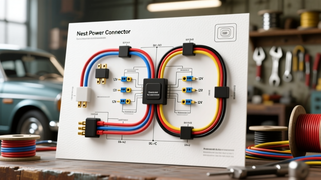
Integrating Smart Climate Control in RVs and Overland Vehicles
Upgrading a motorhome or expedition vehicle with smart home technology is a popular modification in the overland community. However, searching for a nest power connector wiring diagram pdf usually leads to residential HVAC guides that completely ignore the realities of a 12V DC automotive electrical system. The Google Nest Power Connector (Model GA01319-US) is designed to provide a virtual C-wire (Common wire) by utilizing 24VAC from a standard home furnace control board. In an RV, camper van, or heavy-duty truck, you do not have a native 24VAC source. You have a 12V DC house battery bank or a 24V DC chassis system.
To successfully integrate this smart device into a vehicle, off-grid builders must use an isolated DC-to-AC step-up transformer to simulate a residential HVAC control board. When these systems fail, diagnosing the issue requires a deep understanding of both automotive low-tension primary cables and smart home low-voltage control circuits. This guide provides a comprehensive, step-by-step troubleshooting flow specifically engineered for vehicle-mounted smart thermostat installations.
The Vehicle Electrical Challenge: 12V DC vs. 24VAC
According to SAE J1128 standards for low-tension primary cable, automotive wiring is optimized for 12V to 14.4V DC environments. The Nest Power Connector, conversely, expects a stable 24VAC input at 50/60Hz. If you attempt to power the Nest Power Connector using a cheap Modified Sine Wave (MSW) inverter connected to your RV's house battery, the harmonic distortion will cause the internal relay to chatter, overheat, and eventually fail. Furthermore, voltage sags from the vehicle's Battery Isolation Manager (BIM) during engine cranking can drop the 12V system below 10.5V, causing the DC-to-AC transformer to brownout and the Nest thermostat to continuously reboot.
Proper integration requires a dedicated Pure Sine Wave (PSW) micro-inverter or a solid-state 12VDC to 24VAC isolated transformer, wired directly to the RV's house battery distribution bus, completely bypassing the chassis starting battery circuit.
Step-by-Step Troubleshooting Flow
When your RV's smart thermostat displays a 'No Power' error, a blinking red light, or fails to engage the rooftop AC compressor, follow this diagnostic decision tree. You will need a digital multimeter (DMM) capable of measuring True RMS AC voltage and DC voltage.
Phase 1: Verify the DC-to-AC Step-Up Transformer
- Step 1: Locate the 12VDC to 24VAC transformer in your RV's electrical bay.
- Step 2: Set your DMM to DC Volts. Probe the 12V input terminals.
- Reading > 12.5V: House battery is healthy. Proceed to Step 3.
- Reading < 11.5V: Voltage drop detected. Check the 5A ATC inline blade fuse and inspect the 12 AWG TXL wire for corrosion at the busbar.
- Step 3: Set your DMM to AC Volts (True RMS). Probe the 24VAC output terminals.
- Reading 23V - 26V AC: Transformer is functioning correctly. Proceed to Phase 2.
- Reading 0V AC or erratic DC voltage: Transformer has failed or is receiving MSW power. Replace with an isolated marine-grade 24VAC transformer.
Phase 2: Tracing the C-Wire Voltage Drop
- Step 1: Remove the Nest thermostat from the baseplate to expose the 5-wire harness.
- Step 2: Measure AC voltage between the R (Red) and C (Blue/Black) wires.
- Reading ~24VAC: The C-wire circuit is intact. The issue lies within the thermostat baseplate or internal battery.
- Reading < 18VAC: Severe voltage drop. The 18 AWG thermostat wire run is too long or damaged. (See Voltage Drop Math below).
- Step 3: Check continuity between the vehicle chassis ground and the C-wire. There should be NO continuity. The 24VAC system must remain completely floating and isolated from the 12V DC vehicle chassis ground to prevent frying the Nest baseplate logic board.
Reference: RV Nest Power Connector Pinout & Wire Specs
When fabricating the custom harness to bridge your RV's 12V distribution panel to the Nest Power Connector, adhere to the following specifications to ensure fire safety and signal integrity.
| Terminal / Point | Function | Wire Color | AWG Size & Type | Connector / Protection |
|---|---|---|---|---|
| RV House Busbar (+) | 12V DC Input | Red | 12 AWG TXL | 5A ATC Blade Fuse, Ring Terminal |
| RV House Busbar (-) | 12V DC Ground | Black | 12 AWG TXL | Ring Terminal (Do NOT bond to chassis) |
| Transformer to Nest PC | 24VAC Input 1 | White | 18 AWG Stranded THHN | Deutsch DT 2-Pin / Spade |
| Transformer to Nest PC | 24VAC Input 2 | Blue | 18 AWG Stranded THHN | Deutsch DT 2-Pin / Spade |
| Nest PC to Baseplate | C-Wire (Common) | Blue or Black | 18/5 Thermostat Cable | Push-in Baseplate Terminal |
Voltage Drop Calculations for Long Motorhome Runs
In a 40-foot Class A motorhome, the distance from the basement electrical bay to the dashboard thermostat can easily exceed 30 feet (60 feet round-trip). Using standard 18 AWG copper wire (resistance of ~6.385 ohms per 1000 feet), a 60-foot run yields a resistance of 0.38 ohms. If the Nest Power Connector draws 1.5 Amps to charge the internal thermostat battery and engage the AC contactor, the voltage drop is calculated as:
V = I × R
V = 1.5A × 0.38Ω = 0.57 Volts
While a 0.57V drop on a 24VAC system is generally acceptable (leaving ~23.4V at the baseplate), any additional resistance from corroded spade connectors or undersized transformer windings will push the voltage below the 20VAC threshold required by the Google Nest Pro Installation Guide. Always use high-quality stranded copper and crimp connections with dielectric grease to minimize resistance.
Common Failure Modes in Vehicle-Mounted Smart Thermostats
Symptom 1: Pulsing Display or Boot Loops on Rough Terrain
The Cause: Vibration-induced micro-disconnects. RVs experience severe harmonic vibration on washboard roads and highway expansion joints. Standard residential push-in wire connectors on the Nest baseplate rely on spring tension, which can momentarily release 18 AWG solid-core wire under heavy vibration.
The Fix: Never use solid-core wire in a vehicle environment. Always use 18 AWG stranded wire. Furthermore, apply a small dab of marine-grade silicone sealant over the inserted wire terminals on the baseplate to dampen high-frequency vibrations and prevent oxidation.
Symptom 2: Blown Vehicle Inline Fuses Upon AC Engagement
The Cause: Inrush current from the rooftop AC compressor contactor. When the Nest calls for cooling, it closes the Y (Yellow) and C (Common) circuit. This energizes the 24VAC coil of the heavy-duty contactor located on the RV's roof. A failing contactor coil can draw massive inrush current, reflecting back through the DC-to-AC transformer and blowing the 12V DC side fuse.
The Fix: Test the rooftop AC contactor coil resistance. A healthy 24VAC coil should read between 15 and 30 ohms. If it reads near 0 ohms (shorted), replace the contactor. Additionally, ensure your 12V DC input fuse is a time-delay (slow-blow) 5A fuse to handle the brief transformer inrush current without nuisance tripping.
Symptom 3: Inverter Overheating and Shutting Down
The Cause: Using the RV's main 2000W Pure Sine Wave inverter to power the 24VAC transformer via a standard 120V AC outlet. The main inverter requires a massive quiescent current just to remain 'on', draining the house battery rapidly and generating excess heat in the inverter bay.
The Fix: Eliminate the 120V AC middleman. Reference Victron Energy DC Distribution Manuals to wire a dedicated, low-wattage 12VDC to 24VAC solid-state transformer directly to the 12V DC fuse block. This reduces conversion losses, eliminates inverter fan noise, and provides a clean, isolated 24VAC signal exclusively for the smart climate control system.
Sourcing OEM Diagrams and Reference PDFs
Because automotive and smart home ecosystems rarely intersect in official documentation, finding a unified schematic is difficult. When fabricating your custom harness, cross-reference the pinout diagrams provided in the Google Nest Power Connector quick-start guide with your specific RV manufacturer's 12V DC distribution schematics (typically found in the owner's packet from brands like Winnebago, Airstream, or Forest River). Always prioritize isolation between the 12V DC chassis ground and the 24VAC control circuit to protect your vehicle's sensitive CAN bus networks from back-fed AC voltage.