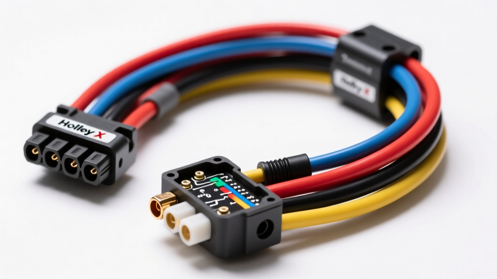
Navigating the Holley Terminator X Wiring Diagram PDF
When upgrading a classic muscle car, hot rod, or project truck to modern electronic fuel injection, downloading the official Holley Terminator X wiring diagram PDF is only the first step. The true challenge lies in selecting the correct engine-specific sub-harness, matching the OEM sensor connectors, and understanding the 60-pin Bosch-style ECU pinout. Unlike universal standalone systems that require hours of crimping and custom loom building, the Terminator X ecosystem relies on modular, plug-and-play harnesses. However, choosing the wrong harness kit or misinterpreting the PDF schematics can lead to catastrophic flyback voltage damage, CAN-bus communication failures, or erratic sensor readings.
This selection guide breaks down the critical differences between the primary Terminator X harness platforms, compares the necessary component selections dictated by the wiring schematics, and provides a technical reference for wire gauges, pinouts, and connector types.
Platform Harness Comparison: LS vs. Coyote vs. SBC
The Holley Terminator X main harness (Part #558-100) remains relatively static, but the engine-specific sub-harnesses vary wildly in pinout, wire routing, and connector selection. Consulting the Holley Terminator X wiring diagram PDF for your specific engine family is crucial before purchasing.
GM LS Platform Harness (558-300 / 558-302)
The LS harness is designed for GM Gen III and Gen IV engines. The primary selection variable here is the reluctor wheel and coil type. The standard 558-300 harness utilizes EV6 USCAR connectors for the fuel injectors and round-style coil connectors. If you are running GM truck coils (D585 square coils), you must select the 558-302 harness or purchase adapter pigtails, as the wiring diagram PDF shows a different pin arrangement for the ignition coil dwell and ground circuits. Furthermore, 58x reluctor engines (Gen IV) require specific cam and crank sensor wiring configurations compared to 24x (Gen III) engines to ensure the ECU achieves proper sequential fuel injection sync.
Ford Coyote 5.0L Harness (558-310)
Wiring a Ford Coyote engine introduces the complexity of Variable Cam Timing (VCT). The Coyote-specific wiring diagram PDF includes dedicated circuits for the VCT solenoids, which are not present on the LS or SBC diagrams. The Coyote harness utilizes Ford-specific USCAR injector connectors and integrates the necessary wiring for the OEM wideband O2 sensors and electronic throttle body (ETB). Selecting this harness requires verifying whether you are using a Gen 1 (2011-2017) or Gen 3 (2018+) Coyote, as the high-pressure fuel pump (HPFP) sensor wiring and ETB pinouts differ significantly in the PDF schematics.
Universal Small Block Chevy (558-102)
For traditional carbureted-style V8 builds converting to EFI, the SBC harness uses Jetronic/Minitimer injector connectors and a bulkhead-style distributor connector. The wiring diagram PDF for this harness focuses on a wasted-spark or sequential ignition setup using a crank trigger and cam sync sensor, rather than relying on an OEM distributor module. Wire routing here is highly custom, requiring careful attention to the 18 AWG sensor ground shielding to prevent ignition noise interference.
ECU 60-Pin Connector Pinout & Wire Gauge Chart
The Terminator X ECU utilizes a sealed 60-pin connector divided into two blocks (A and B). When splicing in custom accessories, aux I/O, or CAN-bus devices, you must adhere to the wire gauge specifications outlined in the Holley Terminator X wiring diagram PDF and SAE J1128 low-tension primary cable standards.
| Function | Pin Location | Wire Color | AWG Size | Connector / Notes |
|---|---|---|---|---|
| Switched 12V Ignition | A1, A2 | Red/White | 18 AWG | Must be clean, ignition-switched 12V source |
| Main Battery Power | A19, A20 | Red | 10 AWG | Direct to battery positive with inline Maxi fuse |
| Main Power Ground | A11, A12 | Black | 10 AWG | Direct to engine block; critical for injector dwell |
| Sensor Ground (Shared) | B14, B15 | Black/White | 18 AWG | Isolated ground for TPS, MAP, IAT, and CTS |
| 5V Sensor Reference | B16 | White/Red | 18 AWG | Shared across all analog sensors; do not overload |
| Injector 1 (Output) | B1 | Pink | 14 AWG | Peak and Hold driver; USCAR/Jetronic connector |
| CAN-Bus High | A38 | White | 18 AWG | Twisted pair with CAN-L; requires 120-ohm resistor |
| CAN-Bus Low | A39 | White/Black | 18 AWG | Shielded twisted pair for dash and WBO2 comms |
Wideband O2 Sensor Selection: Bosch LSU 4.9 vs. 4.2
The Holley Terminator X wiring diagram PDF explicitly supports Bosch Wideband O2 sensors, but selecting the correct sensor generation is vital for harness compatibility. The Terminator X ECU is factory-calibrated and wired for the Bosch LSU 4.9 (5-wire) sensor. The wiring schematic shows a 5-pin Molex connector utilizing specific heater control, pump cell, and calibration resistor circuits.
If you attempt to use an older LSU 4.2 (4-wire) sensor, the pinout will not match the sub-harness connector, and the ECU will fail to read the air/fuel ratio, defaulting to open-loop mode. Always verify the sensor part number (e.g., Bosch 0258017025) against the diagram before installation. Furthermore, the wideband harness wiring must be kept at least 4 inches away from ignition coil power wires to prevent electromagnetic interference (EMI) from skewing the pump cell voltage.
Connector Selection: Metripack vs. USCAR vs. Weatherpak
A major advantage of following the OEM-style Holley Terminator X wiring diagram PDF is the use of industry-standard automotive connectors. Understanding which connector goes where is essential for troubleshooting and harness extension.
- USCAR / Delphi Connectors: Used for fuel injectors and ignition coils on modern LS and Coyote harnesses. These feature a positive locking tab and secondary TPA (Terminal Position Assurance) locks to prevent vibration-induced disconnects.
- Metri-Pack 280 Series: Utilized for engine sensors (MAP, TPS, IAT). These are highly water-resistant and feature varying cavity sizes to prevent cross-plugging. When extending sensor wires, always use the correct Metri-Pack crimp tool to avoid damaging the 18 AWG wire strands.
- Weather-Pack: Often found on the main power/ground relays and older universal harnesses. While bulky, they offer exceptional environmental sealing for under-hood relay mounts.
Common Wiring Mistakes When Using the PDF Schematics
Even with the Holley Terminator X wiring diagram PDF in hand, installers frequently make critical errors during the selection and routing phases. According to technical bulletins from Holley Performance Products, the most common failure modes include:
- Improper Sensor Grounding: Splicing the 18 AWG Black/White sensor ground wire into the chassis ground rather than routing it back to the ECU. This creates a ground loop, causing the 5V reference to fluctuate and the MAP sensor to read erratic boost/vacuum levels.
- CAN-Bus Termination Failures: The Terminator X requires a 120-ohm terminating resistor at each end of the CAN-bus network. If you are running the digital dash and the wideband controller, failing to verify the resistor placement in the wiring diagram will result in 'CAN Error' warnings and data dropouts.
- Ignition Flyback Damage: Using non-resistor spark plugs or failing to wire the coil ground directly to the engine block (as specified in Pin A11/A12) forces the ignition flyback voltage to seek a path through the ECU's internal drivers, permanently damaging the mainboard.
Conclusion
Selecting the right Holley Terminator X harness and components requires more than just matching an engine family; it demands a strict adherence to the wire gauges, pinouts, and connector types detailed in the Holley Terminator X wiring diagram PDF. By comparing your specific engine's requirements against the ECU's 60-pin architecture and utilizing OEM-grade connectors, you ensure a reliable, noise-free EFI system capable of handling everything from street cruising to high-RPM track duty.