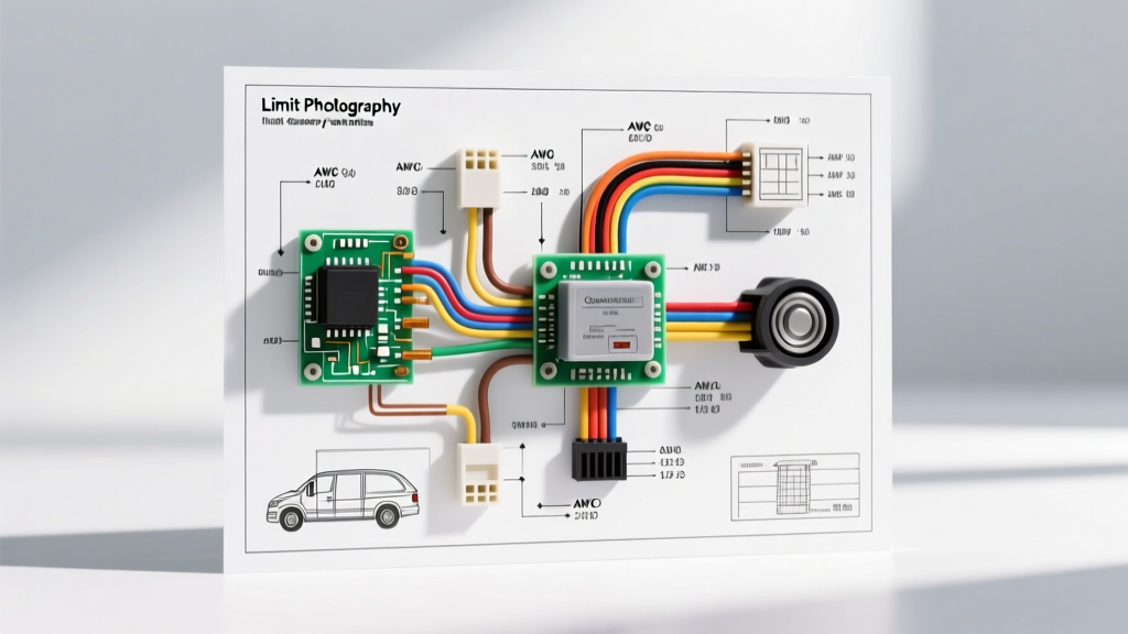
The Role of Limit Switches in Heavy-Duty Truck Accessories
Heavy-duty truck accessories such as hydraulic dump beds, snowplow lifts, motorized winches, and liftgates rely heavily on precision electrical controls to prevent catastrophic mechanical and electrical failures. At the heart of these safety and automation systems is the limit switch. Whether you are upgrading an OEM system or integrating an aftermarket accessory using a vehicle's upfitter circuits, understanding the correct wiring diagram for limit switch applications is critical. A poorly wired limit switch can result in dead-heading hydraulic pumps, over-cranking winch motors, or draining the vehicle's primary battery bank.
In automotive and commercial truck environments, limit switches act as the physical boundary enforcers for electrical circuits. When a mechanical actuator reaches its maximum or minimum travel point, it physically engages the limit switch, altering the circuit's state. This guide provides a comprehensive, practical how-to installation guide for wiring a Single Pole Double Throw (SPDT) limit switch into a heavy-duty truck's 12V DC system, utilizing standard Bosch-style relays and OEM-grade connectors.
Decoding the Wiring Diagram for Limit Switch Circuits
Before cutting any wire or crimping terminals, it is essential to understand the logical flow of the schematic. In a typical truck accessory application, the limit switch does not carry the primary load current. Instead, it is integrated into the low-amperage control circuit of a high-current relay. This prevents the high amperage of a winch or hydraulic pump motor from arcing across the microswitch contacts, which would instantly destroy the switch.
The most reliable wiring diagram for limit switch setups uses an SPDT (Single Pole Double Throw) microswitch. An SPDT switch features three terminals: Common (C), Normally Open (NO), and Normally Closed (NC). In a dump bed or liftgate application, the Common terminal receives switched 12V power from the vehicle's upfitter switch. The NC terminal routes to the 'Raise' relay coil, while the NO terminal can be routed to an indicator light or a secondary 'Lower' relay, depending on the desired fail-safe logic.
Core Components and Relay Logic
To execute this installation, you will need a weather-sealed SPDT limit switch (rated for at least 10A at 12V DC), a standard 5-pin automotive relay, and appropriate gauge wiring. Below is the pinout mapping for integrating the limit switch with a Bosch-style 5-pin relay.
| Component | Pin / Terminal | Function | Wire Color (SAE J1128) | AWG Size |
|---|---|---|---|---|
| 5-Pin Relay | 30 | Main 12V+ Power Input (from Battery/Fuse) | Red | 10 AWG |
| 5-Pin Relay | 87 | Normally Open Output (to Accessory Motor) | Blue | 10 AWG |
| 5-Pin Relay | 87a | Normally Closed Output (Unused in this setup) | N/A | N/A |
| 5-Pin Relay | 85 | Relay Coil Ground | Black | 18 AWG |
| 5-Pin Relay | 86 | Relay Coil 12V+ Input (from Limit Switch NC) | Light Green | 18 AWG |
| SPDT Limit Switch | Common (C) | Switched 12V+ Input (from Upfitter/Dash Switch) | Yellow | 18 AWG |
| SPDT Limit Switch | Normally Closed (NC) | Output to Relay Pin 86 (Active until limit hit) | Light Green | 18 AWG |
| SPDT Limit Switch | Normally Open (NO) | Output to Dash Indicator Light (Limit Reached) | Brown | 18 AWG |
Step-by-Step Installation Guide
Follow these precise steps to ensure a robust, weather-sealed installation that meets commercial vehicle standards.
Step 1: Sourcing Power and Establishing the Primary Circuit
Begin by routing the primary high-current power wire for the accessory motor. Using SAE J1128 compliant GXL wire in 10 AWG, run a lead from the positive battery terminal to the relay's Pin 30. It is imperative to install a time-delay MIDI or ANL fuse within 18 inches of the battery connection to protect against dead shorts. Inductive loads like winch motors create massive voltage spikes; a time-delay fuse prevents nuisance blowing during initial motor startup surges. Terminate the relay's Pin 87 and route it to the accessory motor's positive terminal.
Step 2: Routing the Control Circuit and Upfitter Integration
Modern heavy-duty trucks, such as the Ford F-Series Super Duty or Ram 3500, feature auxiliary upfitter switches. Consult your specific Ford Truck Body Builder Layout Book or equivalent OEM manual to identify a switched 12V+ upfitter circuit. Run an 18 AWG yellow wire from the upfitter switch output to the physical location of your limit switch. Ensure this wire is routed through the firewall using OEM grommets and secured with nylon loom to prevent chafing against the chassis or exhaust components.
Step 3: Terminating the Limit Switch with Weather-Sealed Connectors
Never use open-barrel crimps or standard vinyl butt connectors in under-hood or under-chassis environments. Moisture ingress will cause galvanic corrosion, leading to voltage drop and switch failure. Instead, utilize a TE Connectivity Deutsch DT series connector (specifically the DT06-3S plug and DT04-3P receptacle). Crimp the 18 AWG wires using the appropriate Deutsch solid-core crimp tool, insert the pins into the 3-cavity housing, and ensure the internal wedge lock is fully seated. Connect the Common (C) pin to your yellow upfitter power wire, the NC pin to the light green wire leading to Relay Pin 86, and the NO pin to the brown wire leading to your dash indicator LED.
Step 4: Grounding and Flyback Diode Integration
Connect the relay's Pin 85 to a clean, bare-metal chassis ground using a ring terminal and a self-tapping star washer. Torque the ground bolt to OEM specifications (typically 8-10 Nm for M6 bolts). Because you are switching an inductive relay coil, it is highly recommended to solder a 1N4007 flyback diode across the relay coil pins (85 and 86), with the diode's cathode (stripe) facing Pin 86. This suppresses the reverse voltage spike generated when the relay coil de-energizes, protecting your vehicle's sensitive CAN-bus modules and upfitter switch contacts from arc damage.
Wire Sizing, Connector, and Torque Specifications
Adhering to strict electrical specifications ensures the longevity of the circuit, especially in high-vibration diesel truck environments.
| Parameter | Specification | Application Note |
|---|---|---|
| Primary Load Wire | 10 AWG GXL / SXL | Handles up to 30A continuous; requires adhesive-lined heat shrink. |
| Control Circuit Wire | 18 AWG GXL / TXL | Handles up to 5A; flexible enough for tight firewall routing. |
| Connector Type | Deutsch DT (IP68 Rated) | Mandatory for under-hood/undercarriage limit switch termination. |
| Chassis Ground Torque | 8 - 10 Nm (M6 Bolt) | Must use star washer to bite through paint/e-coat for < 0.05 ohm resistance. |
| Max Voltage Drop | < 0.2V (Control) | Measured from battery positive to limit switch Common terminal under load. |
Advanced Troubleshooting: Decision Tree for Circuit Failures
When a limit switch circuit fails to cut power to the accessory motor, or the relay chatters rapidly, follow this diagnostic decision tree to isolate the fault.
- Symptom: Relay clicks rapidly (chatters) when the limit switch is engaged.
- Cause: Contact bounce or mechanical vibration transferring to the microswitch.
- Fix: Install a 470µF electrolytic capacitor across the relay coil pins (85 and 86) to absorb the micro-second voltage drops caused by contact bounce. Ensure the limit switch actuator arm has a firm, over-travel mechanical stop.
- Symptom: Accessory motor continues to run after the limit switch is physically depressed.
- Cause: Welded relay contacts or limit switch wired to the wrong terminal.
- Fix: Use a digital multimeter to test continuity across the limit switch. If the switch correctly opens the circuit but the motor still runs, the high-current relay contacts have welded together due to arcing. Replace the relay and verify the flyback diode is installed correctly.
- Symptom: Dash indicator light glows dimly even when the limit switch is not engaged.
- Cause: Induced voltage (ghost voltage) from parallel CAN-bus or high-current wiring harnesses.
- Fix: Install a 10k-ohm bleed resistor in parallel with the indicator LED circuit to dissipate induced capacitive coupling voltages.
Environmental Sealing and IP67 Requirements
In commercial truck applications, limit switches are frequently exposed to road spray, de-icing salts, and extreme thermal cycling. Standard industrial microswitches will fail within months in these conditions. Always specify limit switches with an IP67 or IP68 ingress protection rating, featuring a sealed plunger boot and epoxy-potted internal cavities. When mounting the switch to the chassis or hydraulic ram bracket, apply a bead of high-temp RTV silicone around the mounting flange to prevent water from wicking behind the switch housing and corroding the mounting hardware.
By strictly following this wiring diagram for limit switch integration and utilizing OEM-grade termination methods, you ensure that your truck's hydraulic and motorized accessories operate safely, reliably, and in harmony with the vehicle's primary electrical architecture.