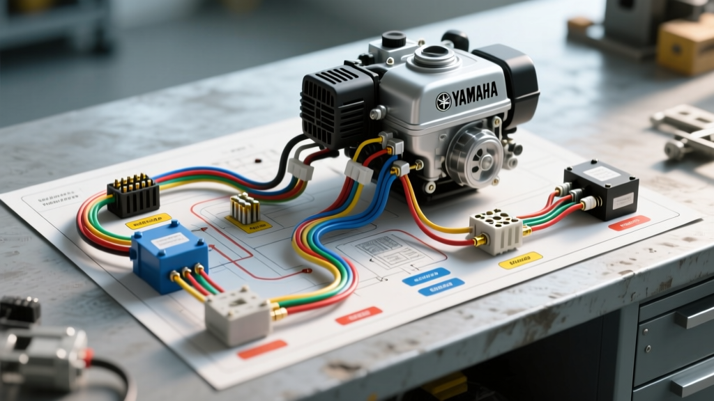
Understanding the Gas Yamaha Golf Cart Wiring Diagram Architecture
When diagnosing, restoring, or modifying a gasoline-powered Yamaha golf cart—specifically the legendary G16, G20, G22, and early Drive models equipped with 301cc or 357cc 4-cycle engines—relying on a standard automotive wiring mindset will lead to immediate frustration. A complete gas Yamaha golf cart wiring diagram reveals a highly distinct electrical architecture. Unlike standard passenger vehicles that utilize a dedicated starter motor and a separate alternator, Yamaha gas carts employ a combined Starter/Generator unit and a magneto-driven Capacitor Discharge Ignition (CDI) system. This walkthrough dissects the OEM schematics, wire color codes, AWG requirements, and real-world failure modes to give you an expert-level understanding of the harness.
The Starter/Generator Circuit: The Heart of the System
The starter/generator is a belt-driven, dual-purpose DC motor mounted to the front of the engine. When the accelerator pedal is depressed, it acts as a high-torque series-wound starter motor. Once the engine fires and RPMs increase, the internal centrifugal switch and voltage regulator transition the unit into a shunt-wound generator to recharge the 12V battery and power accessories.
Terminal Identification and Heavy Gauge Routing
Unlike automotive alternators with a simple B+ and sense wire, the Yamaha starter/generator typically features three or four primary threaded terminals, depending on the exact model year:
- A (Armature): Connects directly to the positive battery terminal via the main solenoid. This carries the highest current load during cranking (often exceeding 150 amps). You must use SAE J1128 compliant 4 AWG or 6 AWG pure copper cable here. Voltage drop on this circuit is the number one cause of slow-cranking complaints.
- F (Field): Connects to the solenoid's motor-facing large terminal. During cranking, the solenoid bridges the battery positive to the Field terminal, energizing the electromagnetic field coils to initiate rotation.
- DF (Differential Field): This is the most misunderstood terminal in the entire gas Yamaha golf cart wiring diagram. The DF terminal routes to the voltage regulator. It controls the generator's output by modulating the field ground path once the cart is running. Connecting 12V+ directly to the DF terminal will instantly fry the internal windings.
Solenoid and Microswitch Logic
Yamaha utilizes a 4-terminal, 12V DC intermittent-duty solenoid to bridge the starter circuit. The two large terminals handle the high-amperage load, while the two small spade terminals control the electromagnetic coil. One small terminal receives switched 12V+ from the ignition key switch. The other small terminal routes to a complex daisy-chain of microswitches: the Forward/Reverse (F&R) microswitch and the accelerator pedal microswitch. The circuit is only completed (grounding the solenoid coil) when the cart is in gear and the pedal is physically depressed. If your cart clicks but won't crank, bypass the microswitches with a jumper wire to isolate a failed limit switch from a dead solenoid coil.
Ignition System: CDI, Exciter, and Kill Circuits
Gas Yamaha carts do not use a traditional 12V automotive ignition coil powered by the battery. Instead, they use a magneto stator plate located under the engine cooling fan to generate high-voltage AC pulses. This AC voltage is rectified and stored in the CDI (Capitor Discharge Ignition) unit, which then dumps it into the ignition coil when the pulser coil signals top dead center (TDC).
CDI Pinout and Wire Colors
The CDI box typically features a 4-pin or 5-pin connector. Understanding these wire colors is critical when reading the wiring diagram:
- Black/Red (Exciter +): Carries high-voltage AC from the stator exciter coil to the CDI. Do not test this with a standard multimeter on the DC voltage setting; it requires a peak-holding DVA (Direct Voltage Adapter) meter to read the 100V-400V output properly.
- White (Exciter - / Ground): The return path for the exciter circuit.
- Black/Yellow (Coil +): High-voltage DC output from the CDI to the primary side of the ignition coil.
- Orange (Kill / Coil -): Routes to the ignition switch and engine kill relay. When the key is turned to OFF, this wire is grounded, shorting the CDI and preventing the spark plug from firing. A frayed Orange wire rubbing against the chassis will cause a mysterious no-spark condition that only happens when the cart hits a bump.
Voltage Regulator and Stator Wiring
The charging system relies on a stator with two distinct winding sets: the exciter winding (for the CDI) and the charging winding. The charging winding outputs raw, unregulated 3-phase or single-phase AC voltage (Yellow and White wires) to the voltage regulator. The regulator rectifies this to DC and clamps the voltage to approximately 13.8V - 14.4V to prevent boiling the battery electrolyte.
The OEM Yamaha 4-pin voltage regulator connector uses the following standard pinout:
- Pin 1 (Red): B+ (Battery Positive). Must be connected to a clean, fused 12V+ source. If this wire has high resistance, the regulator will overcompensate and push 16V+ into the battery.
- Pin 2 (Black): Chassis Ground. Must be ring-terminated directly to the engine block or a clean chassis ground point.
- Pin 3 (White): Sense / Charge Indicator. Often routes to the dashboard charge indicator light or back to the starter/generator DF terminal depending on the specific G-series model.
- Pin 4 (Yellow): AC Input from the stator charging coil.
OEM Wire Color Codes and AWG Specifications
Adhering to proper American Wire Gauge (AWG) sizing is non-negotiable when repairing or extending a golf cart harness. The following table outlines the primary circuits found in the gas Yamaha golf cart wiring diagram:
| Circuit Function | OEM Wire Color | Minimum AWG | Connector / Terminal Type |
|---|---|---|---|
| Battery to Solenoid | Red | 4 AWG | 3/8' Ring Terminal (Heat Shrink) |
| Solenoid to Starter/Gen (A) | Red | 4 AWG | 5/16' Ring Terminal |
| Starter/Gen (DF) to Regulator | Green / White | 16 AWG | 6.3mm Spade (Male) |
| Key Switch to Solenoid Coil | Blue | 14 AWG | 4.8mm Spade (Female) |
| CDI to Ignition Coil | Black/Yellow | 18 AWG | Push-on Boot / Spark Plug Wire |
| Stator AC to Regulator | Yellow | 14 AWG | Weather-Pack Sealed Pin |
| Main Chassis Ground | Black | 6 AWG | 5/16' Ring Terminal (Star Washer) |
Real-World Troubleshooting Decision Tree
Use this diagnostic sequence when the cart's electrical behavior deviates from the schematic logic.
Symptom: Engine Cranks Slowly or Solenoid Rapidly Clicks
- Check Battery Voltage Under Load: A healthy 12V lead-acid battery should not drop below 9.6V during a 15-second crank test. If it drops to 7V, load-test the battery before touching the wiring.
- Perform Voltage Drop Test on A Terminal: Place your multimeter's red lead on the battery positive post and the black lead on the starter/generator 'A' terminal. Have an assistant press the gas pedal. A reading above 0.5V indicates severe corrosion in the 4 AWG cable or failing solenoid contacts. Refer to Buggies Unlimited for OEM-spec heavy-duty replacement solenoids.
- Inspect Belt Tension: The starter/generator relies on the drive belt to transfer torque. A glazed or loose belt will slip, mimicking an electrical voltage drop.
Symptom: Battery Continually Dies (Parasitic Draw or Undercharging)
- Verify Regulator Output: With the engine running at half-throttle, measure DC voltage across the battery terminals. It should read between 13.8V and 14.4V. If it reads 12.2V (battery voltage) or lower, the regulator is not rectifying the stator output.
- Test Stator AC Output: Unplug the Yellow stator wire from the regulator. Set your multimeter to AC Volts. Measure between the Yellow wire and the engine block. At 3000 RPM, you should see 28V to 35V AC. If output is zero, the internal stator charging coil is burnt open, requiring a flywheel puller and stator replacement.
- Check for Parasitic Draw: If the cart charges fine but dies overnight, disconnect the negative battery cable and place an ammeter in series. A draw exceeding 50mA indicates a shorted diode inside the voltage regulator or a stuck microswitch in the F&R column keeping the solenoid coil partially energized.
Expert Tips for Harness Restoration and Environmental Protection
Golf carts operate in brutal environments: high humidity, direct UV exposure, and constant vibration. The factory loom on older G16 and G20 models often becomes brittle, exposing the copper strands to green corrosion (cupric oxide), which acts as a resistor and ruins voltage delivery. When restoring a harness based on your gas Yamaha golf cart wiring diagram, abandon standard vinyl electrical tape. Instead, use adhesive-lined marine-grade heat shrink tubing for all splices and wrap the entire loom in split-loom corrugated tubing secured with UV-resistant nylon zip ties and friction tape. For connector pins, always apply a dab of dielectric grease to prevent moisture ingress, particularly on the low-voltage CDI and microswitch connectors located near the floorboard where water and mud accumulate. For deeper schematic references and model-year-specific variations, consulting archives like Golf Cart Garage can provide supplemental visual diagrams for aftermarket accessory integration, such as LED light bars and voltage reducers, ensuring you tap into the correct switched vs. constant 12V sources without overloading the factory key switch.