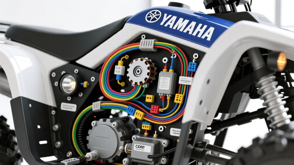
Understanding the YFM350X Electrical Architecture
The Yamaha Warrior 350 (YFM350X), produced from 1987 to 2004, remains one of the most reliable and mechanically sound ATVs ever built. However, its electrical system was designed for a 35-watt halogen headlight and basic ignition functions, not for the high-draw demands of modern off-road modifications. When consulting a wiring diagram for Yamaha Warrior 350 models, you are looking at a split-system architecture: the ignition system runs on a self-generating AC pulse from the stator, while the lighting and accessory circuits run on a separate, unregulated AC lighting coil. This unique setup requires specific modification strategies when adding LED light bars, winches, or heated grips.
Upgrading the electrical system of a Warrior 350 requires a fundamental understanding of its magneto-driven stator. Unlike modern fuel-injected ATVs with high-output three-phase alternators and large lithium-ion batteries, the Warrior relies on a single-phase lighting coil. Attempting to tap directly into the stock headlight wiring to power a 120-watt LED light bar will result in severe voltage drop, flickering, and eventual stator burnout. To execute a proper upgrade and modification project, you must bypass the factory lighting circuit and install a dedicated full-wave rectifier, a regulated DC bus, and heavy-duty relay harnesses.
Core Wiring Diagram for Yamaha Warrior 350: Stator & CDI Pinout
Before splicing into any harness for accessory power, you must understand the source of the electrical generation. The Warrior 350 stator features a source coil (for the CDI) and a separate lighting coil. The factory CDI unit utilizes a 6-pin Sumitomo HM 090 series connector. Understanding these pinouts is critical when diagnosing no-spark conditions after a heavy electrical modification, as voltage drops from poorly wired accessories can starve the CDI of its required trigger signal.
Table 1: Stator Output & CDI Pin Configuration (1987-2004 YFM350X)
| Pin / Wire | Wire Color (OEM) | Function | Voltage / Signal Type | Modification Notes |
|---|---|---|---|---|
| Pin 1 | Black/Red | Source Coil (CDI Power) | 100V - 400V AC (RPM dependent) | Never tap this wire. High voltage will destroy 12V DC accessories instantly. |
| Pin 2 | White/Red | Pickup / Pulse Coil | 0.5V - 2.0V AC Pulse | Keep routing away from high-amp winch cables to prevent EMI interference. |
| Pin 3 | White | Lighting Coil Output | 28V - 45V AC (Unregulated) | Must be routed through a full-wave rectifier for DC LED upgrades. |
| Pin 4 | Black | CDI Ground / Kill Switch | Ground (0V) | Ensure frame ground is clean; poor grounds cause erratic timing. |
| Pin 5 | Orange | Ignition Coil Trigger | 100V+ DC Discharge | Connects directly to the ignition coil primary terminal. |
| Pin 6 | Black/White | Engine Stop / Tether | Ground to Kill | Integrate aftermarket kill switches in parallel with this ground circuit. |
Planning Your Upgrade: The AC to DC Rectifier Conversion
The most common modification for the Warrior 350 is upgrading to modern LED lighting. Because LEDs require steady Direct Current (DC) and the Warrior’s White stator wire outputs raw Alternating Current (AC), you must perform an AC-to-DC conversion. According to the SAE J1128 Standard for low-tension primary cable, automotive wiring must withstand specific thermal and chemical environments, which is why we recommend using 14 AWG GXL (Cross-linked Polyethylene) wire for all new DC harness routing near the engine block.
Step-by-Step Rectifier & Regulator Installation
- Disconnect the Battery: Remove the negative terminal on the 12V battery to prevent short circuits while working on the main harness.
- Tap the Lighting Coil: Locate the White wire exiting the stator casing. Cut the White wire near the main harness plug. Route the stator-side White wire to the AC input terminal of an aftermarket full-wave regulator/rectifier (such as a Trail Tech or Rick's Motorsport Electrics unit).
- Establish a Robust Ground: The Warrior 350 frame is notorious for poor conductivity due to paint and corrosion. Scrape away paint on the frame near the rectifier mounting point, apply dielectric grease, and secure the rectifier ground ring terminal using an M6 bolt torqued to 10 Nm (7.2 ft-lbs).
- Wire the DC Output: Run the DC positive output from the rectifier through a 15A inline maxi-fuse directly to the positive terminal of the battery. This creates a stable 13.8V - 14.2V DC bus capable of powering modern accessories.
High-Draw Accessory Integration: Winch & Light Bar Relays
When adding a 3000-lb winch or a 50-inch LED light bar, you must never route the primary load current through the factory Yamaha handlebar switches. The stock switches are rated for a maximum of 3 amps. Instead, you must use a heavy-duty relay or solenoid contactor, using the factory switched 12V circuit merely as a low-amp trigger signal.
On the Warrior 350, the Brown wire at the main key switch harness provides switched 12V DC power. This is your trigger source. For lighting upgrades, use a standard Bosch-style 4-pin 12V 40A relay. For winch upgrades, you must use a high-amperage solenoid contactor rated for at least 150A continuous duty, as winch stall currents can easily exceed 120 amps.
Table 2: AWG & Fuse Sizing Chart for Warrior 350 Mods
| Accessory Type | Max Draw (Amps) | Recommended Wire Gauge (AWG) | Inline Fuse Rating | Connector Type |
|---|---|---|---|---|
| LED Light Bar (Up to 60W) | 5A | 14 AWG (Primary) / 16 AWG (Trigger) | 10A Blade Fuse | Deutsch DT Series (Waterproof) |
| LED Light Bar (60W - 180W) | 15A | 12 AWG (Primary) / 16 AWG (Trigger) | 20A Blade Fuse | Deutsch DT Series |
| 12V Accessory Port (Cigarette) | 10A | 14 AWG | 15A Blade Fuse | Weather-Pack / Metri-Pack |
| 3000-lb ATV Winch Motor | 120A (Stall) | 6 AWG (Battery to Contactor) | 150A Circuit Breaker | Heavy Duty Ring Terminals (Heat Shrink) |
| Winch Contactor Trigger | 2A | 16 AWG | 5A Inline Glass | Spade / Quick Disconnect |
Executing the Winch Contactor Wiring Diagram
Proper winch wiring is critical for safety and electrical system longevity. Referencing established off-road electrical guidelines from Painless Performance Products, the winch motor must be isolated from the rest of the ATV's sensitive electronics via a dedicated circuit breaker.
- Power Feed: Run a 6 AWG red wire from the positive battery terminal to a 150A marine-grade circuit breaker, then to the large input stud on the winch solenoid contactor.
- Motor Feed: Run a 6 AWG wire from the contactor output stud directly to the winch motor positive terminal.
- Grounding: The Warrior 350's engine is rubber-mounted to the frame, meaning the frame itself is not a reliable engine ground. You must run a dedicated 6 AWG ground wire from the winch motor negative terminal directly to the engine block or the negative battery terminal.
- Trigger Circuit: Wire your handlebar rocker switch to the Brown (switched 12V) wire. Run a 16 AWG wire from the switch to the small trigger spade on the contactor. Ensure a flyback diode is installed across the contactor coil to prevent voltage spikes from frying the CDI when the winch is disengaged.
Troubleshooting Common Modification Failures
Even with a perfect wiring diagram for Yamaha Warrior 350 projects, real-world conditions introduce variables. Here is a diagnostic decision tree for common post-modification electrical issues:
- Symptom: Engine misfires or dies when the winch is engaged.
Cause: Electromagnetic Interference (EMI) from the winch motor brushes disrupting the CDI pulse coil signal.
Fix: Reroute the White/Red pulse coil wire at least 6 inches away from the winch power cables. Install a 0.1µF ceramic capacitor across the winch motor terminals to suppress brush arcing noise. - Symptom: LED lights flicker severely at idle but stabilize at high RPM.
Cause: Insufficient DC capacitance on the rectified lighting circuit.
Fix: Install a 10,000µF 25V electrolytic capacitor in parallel with the DC output of the rectifier to smooth the voltage ripple at low stator frequencies. - Symptom: Headlight dims when the cooling fan or auxiliary lights turn on.
Cause: Voltage drop across the factory ground bus.
Fix: Perform a 'Big 3' grounding upgrade. Run 10 AWG flexible braided copper wire from the stator casing to the frame, from the engine block to the frame, and from the battery negative to the frame.
Final Inspection and Safety Protocols
Before reassembling the plastics and taking the Warrior 350 to the trails, perform a comprehensive voltage drop test. Using a digital multimeter, measure the voltage between the battery positive terminal and the accessory positive input while under load. A reading higher than 0.2V indicates excessive resistance, usually caused by undersized wire or a poorly crimped terminal. Always use adhesive-lined heat shrink ring terminals and a proper ratcheting crimp tool—never rely on solder alone for high-vibration ATV environments, as solder wicks into the wire strands and creates a brittle stress point that will eventually snap. For further OEM reference and exploded parts diagrams, consult the Partzilla Yamaha ATV catalog to verify factory connector part numbers and harness routing clips.