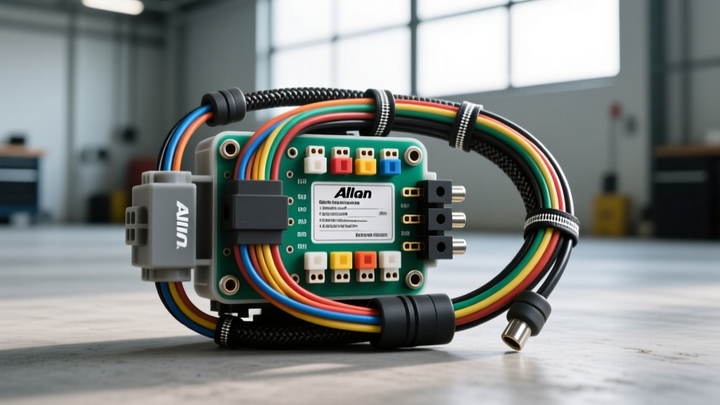
Why Upgrade the OEM Allison External Harness?
When executing a complex drivetrain swap—such as mating a Cummins ISB to an Allison 1000/2000 series transmission, or upgrading a high-horsepower GM Duramax platform—the Allison transmission external wiring harness is frequently the most overlooked component. OEM harnesses are designed for specific factory chassis routing, strict emission component clearances, and moderate underhood temperatures. In a custom modification or swap project, the factory harness often falls short due to inadequate length, brittle aged insulation, or improper heat shielding.
Upgrading to a heavy-duty, custom-fabricated, or aftermarket performance external harness ensures reliable communication between the Transmission Control Module (TCM), the 80-way Vehicle Interface Connector (VIC), and external sensors like the Neutral Start Backup (NSBU) switch. A failure in the external harness doesn't just cause a limp-mode event; it can lead to catastrophic line-pressure drops and burnt clutch packs.
Identifying Your Allison Series and Connector Types
The Allison 1000 and 2000 series transmissions (commonly found in GM, Freightliner, and Navistar applications) utilize a primary 80-way main vehicle interface connector. However, the pin layout and physical connector style changed significantly between generations.
Round Pin vs. Flat Pin 80-Way Connectors
If you are sourcing a harness for an engine swap, matching the TCM generation to the transmission internal wiring is critical. Early Generation 1 through 3 Allison 1000s (approx. 2001-2005) utilized a round-pin 80-way connector. Generation 4 and 5 models (2006-present) transitioned to a flat-pin (blade-style) 80-way connector. Attempting to mate a flat-pin harness to a round-pin transmission case without a dedicated adapter harness will result in severe pin damage and cross-circuit shorts.
- Gen 1-3 (Round Pin): Requires careful extraction tools for depinning; highly susceptible to moisture ingress if the silicone mat seal degrades.
- Gen 4-5 (Flat Pin): Features a superior silicone boot seal and a more robust retaining bolt mechanism. This is the preferred connector style for custom swap harnesses due to its higher vibration resistance.
Technical Specifications and Wire Gauge Requirements
When fabricating or upgrading an Allison external harness, adherence to SAE J1128 standards for underhood automotive wire is non-negotiable. Standard PVC wire will melt when routed near the turbocharger downpipe or exhaust manifolds. You must use Cross-Linked Polyethylene (XLPE) insulated wire, specifically GXL or TXL ratings, which withstand continuous temperatures up to 125°C (257°F).
Below is a reference table for critical circuits found in the GM Duramax application of the Allison 80-way connector. Note that wire colors may vary in Navistar or Freightliner OEM applications, but the AWG and functional requirements remain identical.
| Pin(s) | Circuit Function | Wire Gauge (AWG) | Wire Type | Typical GM Color Code |
|---|---|---|---|---|
| 1, 2, 3 | Switched Ignition (TCM Wake-Up) | 14 AWG | GXL | Pink |
| 4, 5, 38 | Battery Positive (Constant 12V) | 10 AWG | GXL | Red / Orange |
| 6, 7, 8 | Power Ground (TCM & Solenoids) | 10 AWG | GXL | Black |
| 12, 13 | J1939 CAN High / CAN Low | 22 AWG | Shielded Twisted Pair | Dark Green / Light Green |
| 18, 19 | Input/Output Speed Sensors | 20 AWG | Shielded | Purple / Yellow |
| 45-50 | Solenoid PWM Control Circuits | 18 AWG | TXL | Brown / Tan Variants |
Step-by-Step Harness Routing and Shielding for Swaps
In a custom chassis or swap application, the physical routing of the Allison external harness dictates its lifespan. The most common failure mode in swapped Allison 1000s is chafing against the bellhousing lip or heat damage from the exhaust.
Step 1: Bellhousing Clearance and Loom Selection
Never use standard corrugated split-loom tubing in high-vibration areas where the harness crosses the engine block or bellhousing. The rigid plastic edges of split-loom will act like a saw against the wire insulation over time. Instead, wrap the harness in TESA 51036 PET fleece tape or use a woven PET expandable sleeving (Techflex). This provides abrasion resistance without trapping moisture against the wires.
Step 2: Exhaust Heat Shielding
When routing the harness near the turbocharger downpipe or exhaust manifolds, maintain a minimum clearance of 6 inches. If this is impossible due to chassis constraints, the harness must be encased in a fiberglass or basalt sleeve with an aluminized outer layer (rated for 1000°F+ radiant heat). Secure the harness using aluminum Adel clamps (cushion clamps) rather than plastic zip-ties, which will become brittle and snap under thermal cycling.
Step 3: Connector Torque Specifications
The 80-way connector utilizes a central retaining bolt to seat the connector and compress the internal silicone weather seal. According to Allison Transmission service documentation, this bolt must be torqued to exactly 7 Nm (62 lb-in). Under-torquing allows moisture ingress and pin fretting; over-torquing will crack the plastic connector housing or strip the threads on the TCM faceplate.
Upgrading the NSBU Switch Pigtail
The Neutral Start Backup (NSBU) switch, also known as the Manual Lever Position Switch (MLPS), is mounted externally on the side of the transmission case. On Gen 4 and Gen 5 Allison 1000s, this is typically a 7-pin connector. The OEM pigtails are notorious for developing capillary action wicking, where water enters the connector and travels up the wire strands into the TCM, destroying the module.
The Upgrade Fix: When building a custom external harness, eliminate the intermediate NSBU connector entirely if the TCM is mounted in the cab or a protected dry zone. Solder the NSBU wires directly to the harness using adhesive-lined marine-grade heat shrink. If a disconnect is absolutely necessary for transmission removal, upgrade to a sealed Deutsch DT series or Weather-Pack connector, mounted high on the firewall, well above the transmission bellhousing water-line.
TCM Relocation and Grounding Strategies
In many Cummins-to-Allison or LS-to-Allison swap projects, the TCM is relocated from the engine bay to the vehicle cabin to protect it from extreme heat and water fording. When extending the harness through the firewall, use a dedicated, sealed firewall pass-through grommet. Do not rely on the factory engine-block grounds for the TCM power circuits. The GM Upfitter Guidelines explicitly state that high-current modules require dedicated, clean-metal grounding points. Run a dedicated 10 AWG ground wire from the TCM harness ground pins directly to the vehicle battery negative terminal or a dedicated, paint-free grounding bus bar. Relying on the engine block for TCM grounds in a swap application often introduces ground-loop noise, which corrupts the J1939 CAN-bus signals and causes erratic shift scheduling.
Final Inspection and Continuity Testing
Before applying 12V power to a newly fabricated or upgraded Allison external harness, perform a point-to-point continuity test using a digital multimeter. Verify that no solenoid PWM circuits (Pins 45-50) are shorted to the power ground circuits. A shorted solenoid wire will instantly fry the TCM's internal high-side drivers upon key-on. Once continuity and isolation are verified, apply dielectric grease (such as Nyogel 760G) to the 80-way connector face before final mating to ensure long-term corrosion resistance in harsh environments.