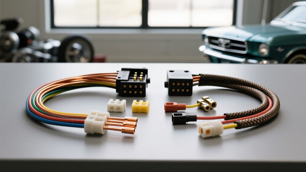
The Critical Role of the 1965 Mustang Wiring Harness in Restorations
When restoring a first-generation Ford Mustang, the electrical system is often the most overlooked and most dangerous component. The original 1965 Mustang wiring harness was wrapped in cloth or early vinyl loom, utilizing copper conductors that are now over half a century old. Heat cycles, vibration, and exposure to engine bay chemicals cause the insulation to become brittle, leading to micro-fractures, voltage drops, and catastrophic short circuits. According to restoration data from Marti Auto Works, electrical fires remain a leading cause of classic car loss, making harness replacement a mandatory step in any ground-up build.
However, selecting the right replacement harness is not a one-size-fits-all decision. Whether you are executing a concours-correct restoration or building a high-amperage restomod with an LS swap and electric cooling fans, understanding the architectural differences between OEM reproductions and modern aftermarket universal kits is essential. This guide breaks down the technical specifications, connector types, and circuit requirements to help you choose the exact harness solution for your 1965 Mustang.
Understanding 1965-Specific Electrical Architecture
The 1965 model year is notorious among Ford restorers for its 'one-year-only' electrical quirks. Unlike the 1966 models that followed, the 1965 Mustang features a unique firewall bulkhead connector and specific dash harness configurations based on the interior trim level.
Dash Harness Variations
You cannot swap a standard 1965 dash harness into a 'Pony' interior or Rally-Pac equipped car without severe modification. The standard sweep-speedometer harness utilizes a completely different printed circuit board and bulb socket configuration compared to the 5-dial instrument cluster found in the GT Equipment Group or Pony interiors. When ordering an OEM-style replacement, you must verify your exact build sheet to ensure the dash harness matches your gauge cluster.
The Firewall Bulkhead Disconnect
The main body harness routes through the firewall via a multi-pin bulkhead connector. The 1965 iteration uses a specific oval-pin layout that is incompatible with 1966-1970 harnesses. Aftermarket universal kits often bypass this bulkhead entirely, requiring you to drill new grommet holes and route wires directly through the firewall—a choice that impacts both concours judging points and firewall integrity.
OEM Reproduction vs. Modern Aftermarket Harness Kits
Choosing between an exact-fit reproduction and a modernized universal chassis harness depends entirely on the end-goal of the vehicle. Below is a technical comparison of the two primary pathways.
| Feature | OEM Reproduction Harness | Modern Aftermarket Chassis Harness (e.g., Painless/American Autowire) |
|---|---|---|
| Wire Insulation | Cloth-braid or early PVC (SAE J1128 Type GXL equivalent) | Modern Cross-Linked Polyethylene (TXL/GXL) for high heat resistance |
| Wire Gauge | Matches factory 14-18 AWG specifications exactly | Upgraded 10-12 AWG for high-draw circuits (headlights, fans) |
| Connectors | Stamped steel, non-weatherproof Motorcraft oval terminals | Sealed Weather-Pack, Deutsch, or modern blade relays |
| Fuse Block | Glass AGC fuses (slow blow, prone to corrosion) | ATEC/Mini blade fuses with dedicated relay triggers |
| Routing | Exact factory routing with original clips and tape wrap | Custom routing, requires fabrication of loom splits and grommets |
For concours judges and purists, the OEM reproduction is the only choice. However, if you are adding a high-output 130-amp 3G alternator, HID headlights, or an aftermarket A/C compressor, the factory 14 AWG headlight circuits and glass fuse block will become a severe bottleneck, necessitating a modernized harness or heavy-duty relay upgrade kits.
Critical Wire Gauge and Circuit Specifications
When evaluating a 1965 Mustang wiring harness, verifying the wire gauge and color codes against the SAE J1128 low-tension cable standards is crucial for safety and troubleshooting. Below are the factory specifications for the primary engine bay and dash circuits.
| Circuit Function | Factory Wire Color | AWG Size | Restomod Upgrade Recommendation |
|---|---|---|---|
| Headlight Power Feed | Black / Yellow Tracer | 14 AWG | Upgrade to 10 AWG with 30A Bosch-style relays |
| Ignition Switch to Coil | Pink (Resistor Wire) | 16 AWG (Resistive) | Bypass with 12 AWG Red/Green if using HEI/PerTronix |
| Alternator Field (1G) | Green / White Tracer | 16 AWG | Retain for 1G; Upgrade to 10 AWG for 3G swap |
| Horn Relay Feed | Yellow | 14 AWG | Retain 14 AWG, add inline 15A blade fuse |
| Floor Dimmer Switch | Red/Black (In), Tan/Green (Out) | 14 AWG | Upgrade to 12 AWG to prevent dimmer switch melting |
The Pink Resistor Wire Warning
One of the most common failures during a 1965 Mustang restoration occurs at the ignition circuit. The factory harness utilizes a specialized Pink resistor wire (1.35 ohms) to drop the 12V battery voltage down to approximately 9V, protecting the points and condenser in the original Autolite distributor. If you are upgrading to a PerTronix Ignitor, MSD 6AL, or GM HEI distributor, this resistor wire must be bypassed or replaced with a standard 12 AWG copper wire. Feeding an electronic ignition module through the Pink resistor wire will cause weak spark, module overheating, and eventual stalling.
Connector Types and Terminal Crimping Standards
The terminal ends used in the 1965 Mustang are predominantly non-sealed, stamped brass or steel 'Motorcraft' style oval barrels, alongside standard bullet connectors for the taillights and marker lights. Proper crimping is where most amateur restorers introduce voltage drop and future corrosion.
- Open-Barrel Terminals: The dash and bulkhead connectors use open-barrel terminals. You must use a specific open-barrel crimping tool (such as the Delphi/Aptiv style crimper) that folds the wire tabs over the conductor and the insulation tabs over the jacket. Using standard pliers or closed-barrel ratchets will crush the terminal, destroying the pin geometry and preventing it from seating in the hard plastic bulkhead housing.
- Bullet Connectors: The rear body harness relies heavily on bullet connectors for the taillights and reverse lamps. Always use nylon-insulated, butt-style bullet connectors with a ratcheting crimper. Apply a small dab of dielectric grease inside the female receiver to prevent moisture ingress, a common cause of '65 Mustang taillight ground failures.
Selection Decision Tree: Which Harness Do You Need?
Use this matrix to determine the correct 1965 Mustang wiring harness configuration for your specific build:
- Concours / MCA Judged Restoration: Purchase exact-fit OEM reproductions (e.g., from YnZ's Yesterdays or NPD). Ensure you specify Standard vs. Pony interior, and Generator vs. Alternator (early '65 6-cylinders used generators; late '65 V8s used the Autolite 1G alternator).
- Mild Restomod (Stock Engine, Modern Accessories): Retain the OEM main harness but install a headlight relay upgrade kit and an alternator upgrade harness (converting from 1G to the internally regulated 3G alternator using 8 AWG charge wires).
- Heavy Restomod / Engine Swap (Coyote, LS, Mega-Squirt): Discard the factory chassis harness entirely. Utilize a universal 22-circuit aftermarket harness. You will need to fabricate custom engine-to-chessis adapter harnesses to mate the modern ECU bulkhead plugs to the new fuse block.
Grounding and Troubleshooting Common 1965 Failures
The 1965 Mustang lacks the dedicated, heavy-duty ground points found in modern vehicles. The factory relied heavily on the engine block grounding through the throttle linkage and motor mounts, which is entirely insufficient for high-amperage alternators.
The Missing Firewall Ground Strap
Every 1965 Mustang left the factory with a braided copper ground strap connecting the passenger side cylinder head or intake manifold directly to the firewall. If this strap is missing, the alternator will attempt to ground through the throttle cable or heater control cables, literally melting them under load. Always install a minimum 4 AWG braided copper ground strap from the engine block to a clean, bare-metal spot on the firewall, and a secondary 10 AWG ground from the engine block to the chassis frame rail.
Taillight Housing Grounds
The rear taillights ground directly through the metal mounting screws into the body quarter panel. Decades of rust and fresh paint jobs often insulate these housings. When installing a new rear body harness, run a dedicated 16 AWG Black pigtail wire from the taillight housing grounding screw directly to a known-good chassis ground, bypassing the reliance on rusty sheet metal.
For further technical documentation on classic Ford electrical routing and bulkhead pinouts, restorers should consult the Painless Performance Wiring Manuals and original Ford Motor Company shop documentation to ensure every circuit is protected and properly fused.