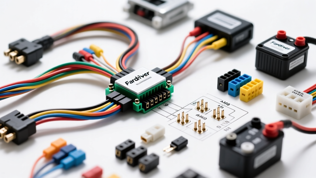
Introduction to Fardriver EV Controller Harnesses
When executing an electric vehicle (EV) swap or upgrading an electric motorcycle, the Fardriver ND-series controllers (such as the ND72530, ND96530, and ND72850) are industry staples. However, the controller is only as reliable as its nervous system. Understanding the Fardriver wiring harness diagram is critical for preventing electromagnetic interference (EMI), avoiding throttle faults, and ensuring high-current safety. This guide compares universal pigtail harnesses, vehicle-specific adapter kits, and CAN-bus integration harnesses, providing the technical depth required for a flawless EV conversion.
Decoding the Fardriver Wiring Harness Diagram
Fardriver controllers typically utilize a split-harness architecture: high-current ring terminals for battery and phase connections, and a multi-pin waterproof connector (often a 35-pin or 20-pin Ampseal-style footprint) for low-voltage logic, sensors, and communications. Misinterpreting the Fardriver wiring harness diagram is the leading cause of blown logic boards and erratic throttle behavior.
High-Current Power and Phase Routing
The high-voltage side of the harness does not use standard plug-and-play connectors; it requires heavy-duty crimped ring terminals. For a 300A+ phase current controller like the ND72530, wire gauge and routing are non-negotiable.
- B+ (Battery Positive): Red, 1/0 AWG or 2 AWG (Silicone insulated, high strand count).
- B- (Battery Negative): Black, 1/0 AWG or 2 AWG.
- Phase U, V, W: Yellow, Green, Blue respectively. Must match the motor hall sensor color sequence to prevent cogging or reverse rotation.
Low-Voltage Signal Connector Pinout
The low-voltage signal harness dictates the controller's behavior. Below is a reference table for the standard 35-pin Fardriver signal connector pinout. Always verify against your specific controller's manual, as firmware revisions can alter auxiliary pin assignments.
| Pin Number | Function | Wire Color | AWG / Spec | Notes |
|---|---|---|---|---|
| 1 | 12V Ignition / Lock | Red | 18 AWG | Switched 12V from vehicle ignition. |
| 2 | Precharge Output | White | 18 AWG | Drives precharge relay; prevents contactor welding. |
| 3 | Throttle Signal | Green | 22 AWG Shielded | Accepts 0.8V to 4.2V analog input. |
| 4 | Throttle 5V Reference | Yellow | 22 AWG | Do NOT short to ground; will fry logic board. |
| 5 | Throttle Ground | Black | 22 AWG | Sensor ground (isolated from power ground). |
| 12, 13, 14 | Hall A, B, C | Yel, Grn, Blu | 22 AWG | Must match motor phase U, V, W sequence. |
| 18, 19 | CAN-H, CAN-L | Orange, Purple | 24 AWG Twisted | Requires 120-ohm termination resistor at ends. |
Harness Kit Comparison: Universal vs. Vehicle-Specific
Selecting the correct harness kit depends entirely on your application. A golf cart retrofit requires vastly different adapter harnesses compared to a CAN-bus integrated automotive EV swap.
| Harness Type | Connector Style | Best Application | Pros & Cons |
|---|---|---|---|
| Universal Pigtail Harness | Unterminated wires with Ampseal pins included | Custom EV motorcycles, karts, and boats | Pros: Maximum routing flexibility. Cons: Requires specialized TE ratcheting crimper. |
| Golf Cart Adapter Harness | OEM-specific plugs (Club Car / EZGO / Yamaha) | Lead-acid to Lithium/Ion golf cart upgrades | Pros: Plug-and-play, no splicing. Cons: Limits auxiliary feature wiring. |
| CAN-Bus Integration Harness | Molex MX150 or Deutsch DT with Y-taps | Automotive EV swaps (using OEM dash clusters) | Pros: Seamless dash telemetry. Cons: Requires complex CAN mapping software. |
Wire Gauge, Shielding, and SAE Standards
When fabricating or extending a Fardriver harness, you must adhere to automotive electrical standards to prevent voltage drop and signal degradation. According to SAE J1128 standards for low-tension primary cable, wire insulation must withstand high under-hood temperatures and chemical exposure. For EV battery and phase cables, we recommend XLPE (Cross-Linked Polyethylene) or high-strand silicone insulation rated for 125°C to 150°C.
For the low-voltage signal harness, EMI from the high-current phase wires can induce 'ghost' voltages in the throttle signal wire, causing the Fardriver controller to throw an Er-08 (Throttle Fault) code. To prevent this, the throttle signal wire (Pin 3) and Hall sensor wires must be routed using shielded twisted-pair (STP) cable, with the shield drain wire grounded exclusively at the controller's logic ground (Pin 5), not the chassis ground.
Product Selection: Crimping Tools and Connector Housings
If you are building a custom harness from a universal Fardriver pigtail kit, the integrity of your crimps is paramount. The waterproof housings typically utilize TE Connectivity Ampseal or similar 1.2mm/1.5mm terminal systems. Using standard electrical pliers will result in high-resistance crimps that melt under the continuous 5A-10A draw of auxiliary relays and cooling fans.
Selection Checklist for Custom Harness Fabrication:
- Crimper: Use a ratcheting terminal crimper calibrated for 1.2mm/1.5mm non-insulated pins (e.g., IWISS SN-28B or TE equivalent).
- Seals: Never forget the silicone weather seals. They must be slid onto the wire before crimping the terminal.
- Extraction Tool: Purchase the specific plastic extraction tool for the 35-pin housing. Pushing a pin in without the proper tool often folds the locking tang, resulting in a backed-out pin that causes intermittent hall sensor failures.
Troubleshooting Common Harness Faults
Even with a perfect Fardriver wiring harness diagram, real-world installations encounter issues. Use this diagnostic tree to resolve common harness-related faults:
- Symptom: Controller powers on, but motor stutters or spins backward.
Cause: Phase and Hall sensor mismatch.
Fix: Verify that Phase U (Yellow), V (Green), and W (Blue) exactly match Hall A (Yellow), B (Green), and C (Blue). If using a non-standard motor, use the Fardriver PC software to run the 'Auto-Learn' angle detection routine. - Symptom: Er-08 Throttle Fault immediately upon key-on.
Cause: Throttle signal voltage is outside the 0.8V - 4.2V safety window, often due to EMI or a bad sensor ground.
Fix: Check Pin 5 (Throttle Ground) for continuity to the battery negative. Ensure the throttle signal wire is not zip-tied parallel to the B+ or Phase cables. - Symptom: Main contactor clicks rapidly or welds shut.
Cause: Precharge circuit harness is bypassed or incorrectly wired.
Fix: Ensure Pin 2 (Precharge Output) is wired to the precharge relay coil, and that a 150W 100-ohm precharge resistor is installed in parallel with the main contactor before the controller capacitors receive full voltage.
Authoritative References & Sourcing
Designing a reliable EV harness requires adherence to proven automotive and electrical standards. For further reading on EV component sourcing, wiring standards, and high-current termination practices, consult the following resources:
- SAE International - J1128: Low Tension Primary Cable Standard (Crucial for selecting correct wire insulation for under-hood EV environments).
- TE Connectivity - Ampseal Connector Systems (Technical datasheets for waterproof automotive connector crimp specifications and pull-out force testing).
- EV West - EV Conversion Components & Harnesses (Industry-leading supplier of adapter harnesses, contactors, and precharge circuits for Fardriver and competing EV controllers).
By strictly following the Fardriver wiring harness diagram, utilizing proper SAE-rated wire gauges, and selecting the correct adapter kit for your specific chassis, you ensure a safe, reliable, and high-performance electric drivetrain.