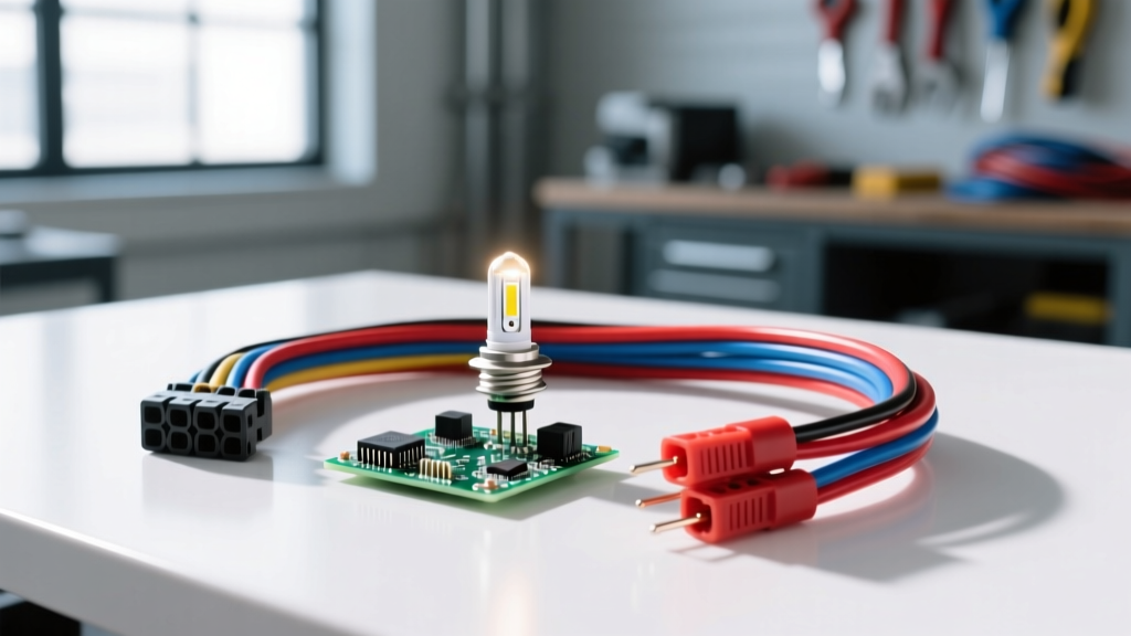
Upgrading to LEDs: Why the Factory Harness Isn't Enough
Swapping out dim, yellow halogen bulbs for crisp, high-output LEDs is the most popular lighting modification in the automotive world. However, simply plugging an LED bulb into a factory headlight connector often results in frustrating issues: strobing lights, dashboard error codes, or even melted factory wiring. This is where a purpose-built Diode Dynamics wiring harness becomes an absolute necessity for any beginner or seasoned gearhead. Unlike generic, unshielded adapters found on bargain sites, a premium harness bridges the gap between legacy analog vehicle circuits and modern solid-state LED technology, ensuring safe, reliable, and error-free illumination.
For beginners, it is crucial to understand that modern vehicles do not send a simple, steady 12-volt stream to the headlights. The factory wiring was designed for the specific electrical characteristics of tungsten-halogen filaments. When you introduce LEDs into this ecosystem, you are fundamentally changing the electrical load and signal response. To fix this, we must understand the two primary culprits of LED failure: Pulse Width Modulation (PWM) and CANbus monitoring.
The Core Problems: PWM Flicker and CANbus Errors
1. Pulse Width Modulation (PWM) Flickering
Many modern vehicles, particularly Chrysler, Jeep, Dodge, GM, and European models built after 2014, use Pulse Width Modulation to control lighting circuits. Instead of sending a steady 12V-14.4V DC signal, the Body Control Module (BCM) pulses the voltage on and off at high frequencies (typically 200Hz to 400Hz) to reduce power consumption and heat.
A standard halogen bulb has high thermal inertia; the tungsten filament stays hot and glowing during the 'off' micro-cycles, making the pulsing invisible to the human eye. LEDs, however, react in nanoseconds. When the PWM signal drops to zero, the LED instantly turns off, resulting in a violent strobe or flicker effect. A high-quality Diode Dynamics wiring harness integrates inline capacitors or relay isolation to smooth out these pulses, delivering steady DC power to the LED driver.
2. CANbus 'Bulb Out' Warnings
The Controller Area Network (CANbus) is the nervous system of your vehicle. The BCM constantly monitors the current return on lighting circuits to detect blown bulbs. A factory H11 halogen bulb draws roughly 55 Watts (approximately 4.5 Amps at 12V). An equivalent high-performance LED might only draw 18W to 25W (1.5A to 2.0A).
When the BCM detects that the circuit is pulling less than 3 Amps, it assumes the filament has snapped. It then triggers a 'Bulb Out' warning on your dashboard and, in many cases, completely cuts power to the circuit to prevent a perceived short. CANbus decoders built into specialized harnesses introduce precise electrical resistance or active IC chips to mimic the 4.5A draw of a halogen bulb, keeping the BCM happy and the power flowing.
Decoding the Diode Dynamics Wiring Harness Lineup
Choosing the right harness depends on your vehicle's specific electrical architecture. According to the Diode Dynamics Technical Information portal, selecting the correct interface is critical for long-term reliability. Here are the three main types of harnesses you will encounter:
- PWM Anti-Flicker Capacitors (Inline Modules): These are compact, inline cylinders containing high-capacity electrolytic capacitors (typically 4700µF to 10000µF). They plug directly between the factory H11 or 9005 connector and the LED bulb, absorbing the PWM spikes and releasing a steady voltage. They are ideal for vehicles with mild PWM but no strict CANbus current monitoring.
- Heavy-Duty Relay Harnesses (H4, H11, 9005): This is the gold standard for older vehicles with marginal factory wiring (like 1990s-2000s Honda, Toyota, and Nissan trucks). A relay harness uses the factory headlight plug merely as a low-amperage 'trigger' signal to switch a heavy-duty automotive relay. The relay then pulls clean, high-amperage power directly from the battery, bypassing the factory headlight switch entirely.
- CANbus Active Decoders: Unlike cheap load resistors that generate massive amounts of waste heat, active decoders use integrated circuits to simulate the exact startup inrush current and steady-state draw of a halogen bulb without the thermal dangers of wire-wound resistors.
Technical Specifications & Wire Sizing Guide
When fabricating or installing a harness, wire gauge (AWG) and connector integrity are paramount. Undersized wires lead to voltage drop, dim lights, and melted insulation. Below is the specification chart for standard LED relay and adapter harnesses:
| Harness Type | Application | Wire Gauge (AWG) | Connector Type | Current Rating |
|---|---|---|---|---|
| PWM Capacitor Module | Inline H11 / 9005 / 9006 | 18 AWG (Stranded) | Molex MX150 Sealed | 5A Peak |
| H4 Dual-Beam Relay | Headlights (7" Round / 5x7) | 14 AWG (Power) / 18 AWG (Trigger) | H4 P43t-38 / Ring Term | 30A Continuous |
| CANbus Decoder | Turn Signals / DRL / Fog | 16 AWG (Stranded) | T20 (7443) / BAU15s | 25W Load (2A) |
Understanding the H4 Relay Pinout and Wire Colors
If you are installing an H4 relay harness for a Jeep Wrangler or classic Toyota pickup, you must understand the pin configuration. The H4 (P43t) connector features three pins:
- Pin 1 (Center/Top): Ground (-). Wire Color: Black.
- Pin 2 (Left/Bottom): Low Beam Trigger (+). Wire Color: Yellow or Red.
- Pin 3 (Right/Bottom): High Beam Trigger (+). Wire Color: Green or White.
The harness will route these triggers to a standard Bosch-style ISO Mini Relay. The relay pinout is as follows: Pin 85 (Coil Ground), Pin 86 (Coil 12V Trigger from factory H4 plug), Pin 30 (Common 12V+ from Battery via inline fuse), and Pin 87 (Normally Open Load output to the LED headlights). For a deeper dive into relay load capacities and coil resistance, refer to Littelfuse Automotive Relay specifications.
Step-by-Step Installation: Best Practices for Beginners
Proper installation of your Diode Dynamics wiring harness ensures longevity and prevents electrical fires. Follow these expert steps:
- Isolate the Power: Always disconnect the negative battery terminal using a 10mm wrench. Tuck the cable away from the post to prevent accidental reconnection while routing wires.
- Route and Protect: Never run harness wires near exhaust manifolds, steering shafts, or sharp firewall edges. Wrap the 14 AWG power wires in split-loom tubing or Tesa tape to protect against abrasion and under-hood heat.
- Establish a True Ground: A poor ground is the #1 cause of headlight flicker. Do not simply bolt the ground ring terminal over painted metal or factory e-coat. Use a Dremel or sandpaper to expose bare, shiny steel. Secure the ring terminal with a stainless steel star washer to bite into the metal, and apply a dab of conductive dielectric grease to prevent oxidation.
- Fuse Protection: Ensure the inline fuse holder on the 14 AWG battery feed wire is within 6 inches of the battery positive terminal. Use a 15A or 20A ATO blade fuse depending on your total LED wattage draw.
- Seal the Connections: Apply a small amount of silicone dielectric grease inside the Molex MX150 or H4 connectors before mating them to the LED bulbs. This prevents moisture intrusion and galvanic corrosion between the copper harness terminals and the aluminum bulb heat sinks.
Troubleshooting Common LED Harness Issues
Even with a premium harness, beginners may encounter a few quirks. Here is how to diagnose them:
Radio Interference (EMI)
Symptom: Your AM/FM radio buzzes or loses reception when the headlights or fog lights are turned on.
Cause: Cheap LED drivers act as broadband RF transmitters, leaking Electromagnetic Interference (EMI) into the vehicle's antenna wiring.
Fix: Ensure you are using a shielded Diode Dynamics wiring harness. Premium harnesses integrate ferrite beads and braided shielding to comply with strict SAE J1113 Electromagnetic Compatibility standards. If using an unshielded harness, wrap the LED driver pucks in copper foil tape and ground the foil.
Turn Signal Hyperflashing
Symptom: LED turn signals blink twice as fast as normal.
Cause: The factory thermal flasher relay relies on the high heat generated by 21W halogen bulbs to bend a bimetallic strip. LEDs run cool and draw low current, so the strip never bends correctly, causing rapid cycling.
Fix: Swap the factory thermal flasher for an electronic LED flasher relay (often a 3-pin or 4-pin plug under the dash). If your vehicle uses a BCM-controlled flash rate with no physical relay, you must install 6-ohm, 50W load resistors in parallel with the LED harness to simulate the halogen current draw.
Final Thoughts on Harness Selection
Investing in a high-quality Diode Dynamics wiring harness is not just about making your LEDs work; it is about protecting your vehicle's expensive Body Control Module from voltage spikes and backfeeding. By understanding the fundamentals of PWM, CANbus logic, and proper wire gauging, you can confidently tackle any LED lighting upgrade. Always verify your specific bulb size (e.g., H11 vs H11B, which feature different locking tabs and pin orientations) before ordering, and take the time to route and ground your harness with OEM-level precision.