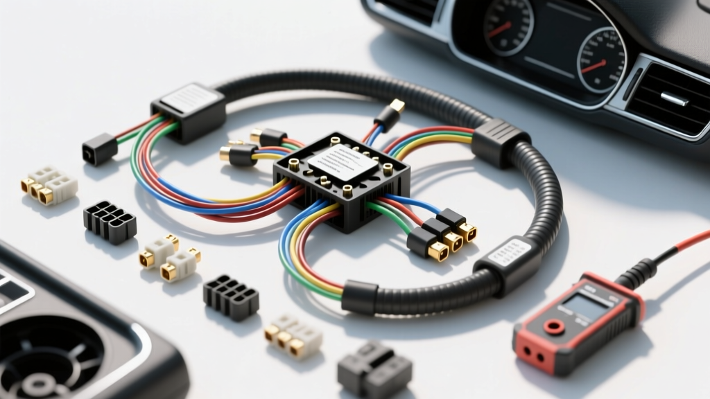
The Real Cost: How Much Is a Wiring Harness Replacement?
When an electrical gremlin traces back to a melted firewall bulkhead, a chafed engine harness, or corroded chassis grounds, the first question owners and technicians ask is: how much is a wiring harness replacement? The answer is rarely a simple flat rate. The cost varies wildly depending on whether you are replacing a localized sub-harness, a full engine bay harness, or the main body/chassis harness that snakes through the dashboard and firewall.
On average, an OEM engine wiring harness costs between $400 and $1,200 for the part alone. However, labor is where the true expense lies. Book time for an engine harness swap typically ranges from 4 to 10 hours, depending on whether the intake manifold, alternator, and ECU must be removed to access the firewall connectors. At an average shop rate of $120 to $180 per hour, labor can easily add $500 to $1,800 to your final bill.
Conversely, a full body or chassis harness replacement—which requires complete dashboard removal, steering column drop, and HVAC evacuation—can push parts costs over $2,500 and labor well past 25 hours. Because of these staggering costs, many DIYers attempt to repair or splice damaged sections. While repairing a single 18-AWG sensor wire is viable, attempting to patch a brittle, 20-year-old main harness often leads to catastrophic electrical failures. Below, we break down the critical safety warnings and costly mistakes you must avoid when tackling a harness replacement.
Critical Safety Warnings Before You Unplug a Single Pin
Automotive wiring is not just about making connections; it is about managing volatile energy sources. Failing to observe proper safety protocols can result in severe injury or thousands of dollars in module damage.
1. The SRS (Airbag) Circuit Danger
Any wire wrapped in yellow sleeving or terminating in a yellow connector is part of the Supplemental Restraint System (SRS). These circuits operate on squibs that require very little current to ignite the pyrotechnic charge in an airbag or seatbelt pretensioner.
The Rule: Never probe an SRS wire with a test light or standard multimeter. The internal battery in a multimeter can provide enough micro-amps to deploy the airbag. Always disconnect the negative battery terminal and wait a minimum of 15 minutes for the backup capacitors in the SRS module to drain before touching yellow connectors. Furthermore, SRS connectors feature internal shorting bars that bridge the pins when unplugged to prevent static electricity deployment. Never bypass these.
2. High-Voltage (HV) Hybrid and EV Systems
If you are working on a hybrid or EV, orange cables indicate high-voltage DC circuits ranging from 300V to over 800V. A shock from an intact orange harness can be lethal. Replacing an HV harness requires certified high-voltage gloves (Class 0), a lockout/tagout procedure on the manual service disconnect (MSD), and a CAT III or CAT IV multimeter to verify zero potential before touching any shielding.
3. ECU and PCM Protection
Modern Engine Control Units (ECUs) are highly sensitive to voltage spikes. If you unplug a harness connector while the battery is still connected, or if you accidentally cross a 12V power feed with a 5V reference signal, you will instantly fry the internal driver transistors in the ECU. Always disconnect the negative battery ground first, and secure it away from the battery post before beginning harness removal.
5 Costly DIY Mistakes That Turn a $500 Job into a Nightmare
Mistake 1: Forcing Locked Connectors and Breaking TPA Tabs
Modern OEM connectors (like the Delphi Metri-Pack or TE Connectivity AMP series) utilize Terminal Position Assurance (TPA) and Connector Position Assurance (CPA) locks. These are small plastic wedges or slides that prevent the metal terminal from backing out. Forcing a connector apart without releasing the TPA will snap the locking tang off the terminal. The wire will then back out of the connector while driving, causing an intermittent open circuit that is a nightmare to diagnose. Always use dedicated terminal release tools (like the Lisle 39410 set) to depress the tangs properly.
Mistake 2: Using the Wrong Wire Insulation (PVC vs. TXL/GXL)
Many DIYers buy cheap PVC wire from a hardware store to repair an engine harness. Standard PVC (SAE Type T3) melts at around 105°C (221°F). Under-hood temperatures near exhaust manifolds easily exceed this, causing the insulation to melt and short against the engine block. You must use GXL or TXL cross-linked polyethylene wire, which withstands temperatures up to 150°C (302°F) and features a much thinner, tougher wall. For routing near turbochargers or exhaust headers, the harness must be wrapped in fiberglass or silica heat-sleeving.
Mistake 3: Soldering Under-Hood Connections
Soldering creates a rigid, brittle joint. In an engine bay subject to constant vibration and thermal expansion, soldered wire joints will eventually suffer from work-hardening and snap. According to SAE J1128 standards and OEM repair procedures, under-hood splices must be crimped using a proper ratcheting crimper and sealed with dual-wall, adhesive-lined heat shrink (DWFR). The inner meltable adhesive creates a waterproof seal, preventing capillary action from drawing moisture into the harness.
Mistake 4: Ignoring Wire Gauge (AWG) Upgrades for High-Draw Circuits
If you are replacing a harness due to a melted cooling fan or fuel pump circuit, simply replacing it with the same factory wire gauge is a mistake. OEM engineers often undersize wires to save weight and cost. If a cooling fan draws 25 amps continuously, the factory 12-AWG wire may overheat in high ambient temps. Upgrading high-draw circuits to 10-AWG GXL wire and upgrading the corresponding Metri-Pack 280 terminals to handle the larger gauge will prevent the new harness from melting in the future.
Mistake 5: Routing Harnesses Without Drip Loops
When plugging a new harness into a firewall bulkhead or an ECU located in the engine bay, failing to create a 'drip loop' (a slight downward curve in the wire before it enters the connector) allows water to run down the wire directly into the connector cavity. Over time, this causes green corrosion on the brass terminals, increasing resistance and causing sensor signal dropouts.
Harness Replacement Cost & Complexity Matrix
| Harness Type | Est. OEM Part Cost | Labor Hours | Risk Level | Common Failure Point |
|---|---|---|---|---|
| Engine Main Harness | $400 - $1,200 | 4 - 8 hrs | Medium | Chafing near valve cover / Alternator output wire melting |
| Injector / Coil Sub-Harness | $80 - $250 | 1 - 3 hrs | Low | Brittle insulation from heat soak; connector tab breakage |
| Body / Chassis Harness | $1,200 - $2,800 | 15 - 30 hrs | High (SRS/HVAC) | Firewall bulkhead corrosion; kick-panel kick-kicks |
| Tail Light / Rear Harness | $150 - $400 | 2 - 5 hrs | Low | Trunk hinge pinch points; water ingress in lamp sockets |
When to Repair vs. Replace: The 20% Rule
Professional automotive electricians follow a general guideline: if more than 20% of the circuits in a specific harness loom show signs of brittle insulation, cracked loom tubing, or terminal corrosion, the entire harness should be replaced. Splicing a new wire into a harness where the surrounding wires are suffering from copper oxidation (black wire syndrome) is a temporary fix. The resistance will simply shift to the next weakest link in the circuit.
For localized damage, such as a rodent chewing through a single O2 sensor harness, utilize OEM-style weather-sealed connectors. Strip the wire using a precision wire stripper that will not nick the copper strands (nicking reduces the cross-sectional area and creates a hot spot). Crimp the terminal using a tool specifically calibrated for the terminal family—using a generic crimper on a Delphi Metri-Pack 280 terminal will result in a poor bellmouth crimp, leading to a high-resistance connection that will eventually melt the plastic connector housing.
Final Safety Checklist Before Reconnecting Power
- Verify all TPA and CPA locks are fully seated (you should hear/feel a distinct click).
- Ensure all ground ring terminals are bolted to bare, unpainted metal. Use a wire brush to clean the chassis ground point, and apply a dab of dielectric grease over the top of the bolt to prevent future corrosion.
- Double-check that the ECU, TCM, and BCM connectors are fully seated and their lever-locks are engaged.
- Reconnect the battery ground and perform a module reset/scan to clear any low-voltage codes thrown during the repair.
Understanding exactly how much a wiring harness replacement costs—and respecting the severe safety risks involved—will save you from turning a routine electrical repair into a catastrophic vehicle failure. Always prioritize OEM-grade materials, proper crimping techniques, and strict adherence to high-voltage and SRS safety protocols.