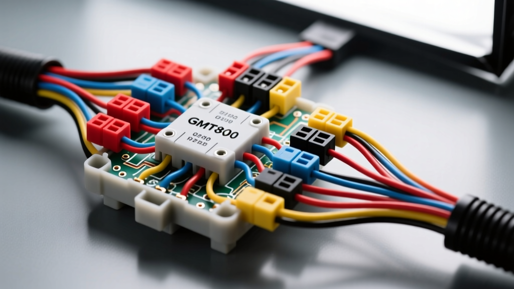
Decoding the GMT800 Underhood Fuse Box Wiring Harness
The 1999-2006 GM GMT800 platform (Silverado, Sierra, Tahoe, Suburban, and Avalanche) utilizes an Underhood Bussed Electrical Center (UBEC) that serves as the primary power distribution node for the entire vehicle. Unlike traditional fuse boxes that merely hold glass fuses, the GMT800 UBEC is a complex, multi-layered printed circuit board (PCB) integrated directly with a massive, high-amperage fuse box wiring harness. Because this harness routes power to critical systems—including the ignition switch, HVAC blower motor, ABS module, and fuel pump relay—it is subjected to extreme thermal cycling and environmental exposure. Understanding the complete wiring diagram and pinout configuration of this harness is essential for diagnosing parasitic draws, intermittent electrical failures, and the notorious 'melted connector' issues common to this generation.
Anatomy of the UBEC Harness Connectors
The underside of the GMT800 UBEC interfaces with the main chassis harness via three primary multi-pin connectors, designated C1, C2, and C3. These connectors utilize Delphi (now Aptiv) Metri-Pack terminal systems, chosen for their robust weather seals and high-current capabilities. However, the physical design of the UBEC enclosure often traps moisture against these terminals, leading to fretting corrosion and increased electrical resistance.
Connector C1: The Heavy Duty Power Feeds
Connector C1 handles the main battery feeds and high-amperage accessory circuits. The terminals here are predominantly Metri-Pack 630 series, designed to handle continuous loads exceeding 40 amps. The wires in this loom are typically 4 AWG and 8 AWG, featuring thick cross-linked polyethylene (XLPE) insulation that meets SAE J1128 standards for under-hood primary cable. The primary failure mode in C1 is not usually terminal melting, but rather insulation chafing against the inner fender liner where the harness zip-ties degrade over time.
Connector C2: The Infamous 'Melt Zone'
Connector C2 is the most critical and problematic interface on the GMT800 fuse box wiring harness. It routes the Ignition 1 (IGN A) and Accessory feeds to the cabin. The IGN A circuit powers the HVAC blower relay, the ignition switch, and multiple interior fuse block feeds. GM utilized a 10 AWG Pink wire for this circuit, terminating into a Metri-Pack 280 female terminal. Because the continuous draw of the HVAC system and interior modules frequently pushes 25-30 amps through a single 280-series terminal, any minor corrosion creates a high-resistance junction. This resistance generates heat, which softens the nylon connector housing, leading to terminal push-out, arcing, and ultimately, a melted fuse box harness pigtail.
Complete C2 Connector Pinout & Wire Color Chart
When performing a diagram walkthrough or replacing the C2 pigtail, accurate pin identification is mandatory. The C2 connector is a 7-cavity block. Below is the definitive pinout specification chart for the GMT800 UBEC C2 harness interface.
| Pin | Wire Color | AWG | Circuit Function | Terminal Type |
|---|---|---|---|---|
| A | Pink | 10 | IGN A Feed (HVAC Blower, Ign Sw) | Metri-Pack 280 F |
| B | Orange | 10 | BAT Feed (Accessory Delay, RAP) | Metri-Pack 280 F |
| C | Dark Green | 12 | HVAC Compressor Clutch Relay Ctrl | Metri-Pack 150 F |
| D | Yellow | 12 | ABS Module Ignition Feed | Metri-Pack 150 F |
| E | Black | 10 | Main UBEC Ground Return | Metri-Pack 280 F |
| F | Light Blue | 14 | PCM / ECM Wake-Up Signal | Metri-Pack 150 F |
| G | White | 12 | Fuel Pump Relay Control Feed | Metri-Pack 150 F |
Step-by-Step Diagram Walkthrough: Tracing the IGN A Feed
To effectively troubleshoot a voltage drop or a melted connector, you must trace the circuit from the source to the load. Here is the step-by-step walkthrough of the IGN A (Pin A) circuit.
- Source (Battery to Mega Fuse): Power leaves the positive battery terminal via a 4 AWG Red cable, traveling to the 175A Mega Fuse located in the underhood junction block.
- Mega Fuse to UBEC Internal Bus: From the Mega Fuse, power enters the UBEC through the C1 connector (Pin B, 4 AWG Red). It flows through the internal PCB copper traces to the IGN A relay bus.
- Internal Bus to C2 Connector: The PCB routes the current to the male blade of the C2 connector, Pin A. This is the exact physical junction where the harness-side female Metri-Pack 280 terminal mates with the UBEC.
- C2 Pin A to the Cabin: The 10 AWG Pink wire exits the UBEC, travels through the main harness loom down the driver-side frame rail, and passes through the rubber grommet in the firewall.
- Load Distribution: Once inside the cabin, the Pink IGN A wire splices into the left-side instrument panel harness, feeding the HVAC blower motor relay coil and switch, the ignition switch main power feed, and the power window circuit breaker.
Diagnostic Procedures: Voltage Drop Testing the Harness
Never rely solely on a visual inspection of the fuse box wiring harness. Fretting corrosion occurs inside the terminal crimp and mating surfaces, invisible to the naked eye. To diagnose high resistance in the C2 connector, perform a dynamic voltage drop test.
- Setup: Set your digital multimeter (DMM) to DC Volts. Turn the ignition to the 'RUN' position and engage the HVAC blower motor on the highest speed setting to place a heavy load on the IGN A circuit.
- Measurement: Place the red DMM probe on the UBEC-side male blade for Pin A (accessed from the top PCB side if possible, or back-probe the fuse slot). Place the black DMM probe on the harness-side 10 AWG Pink wire, piercing the insulation about one inch from the C2 connector backshell.
- Interpretation: According to ASE Education Foundation electrical standards, a maximum acceptable voltage drop across a single connection point is 0.1V. If your DMM reads 0.2V or higher, the Metri-Pack 280 terminal has excessive resistance and is generating destructive heat. A reading over 0.5V confirms imminent thermal failure.
Harness Repair and Terminal Replacement
If the C2 connector housing is melted, or the voltage drop test fails, you must replace the harness pigtail and terminals. Do not attempt to solder the wires directly to the UBEC pins; the heat will delaminate the PCB traces. Instead, use a proper depinning tool and crimp new terminals.
The Metri-Pack 280 series requires a specific crimp profile. Using a generic open-barrel crimper will result in a poor mechanical grip and high electrical resistance. You must use a tool calibrated for Aptiv Metri-Pack 280 terminals, ensuring the wire bellmouth and insulation grip are formed to factory specifications. After crimping, apply a small amount of Nyogel 760G dielectric grease to the terminal mating surfaces before inserting them into a new, heavy-duty nylon C2 connector shell. This grease displaces moisture and prevents the galvanic corrosion that causes the initial resistance spike.
Preventative Maintenance: Sealing the UBEC
The GMT800 UBEC lid relies on a foam weatherstrip that degrades rapidly under UV exposure and engine bay heat. Once this seal fails, water ingress accelerates harness degradation. When reinstalling the fuse box wiring harness, inspect the secondary locking mechanism (TPA - Terminal Position Assurance) on the C1, C2, and C3 connectors. If the TPA is broken, vibrations will cause the terminals to back out, leading to arcing. Finally, apply a bead of clear RTV silicone around the perimeter of the UBEC base where it meets the fender well bracket, ensuring the mounting nuts are torqued to exactly 9 Nm (80 lb-in) to prevent stress fractures on the harness strain reliefs.