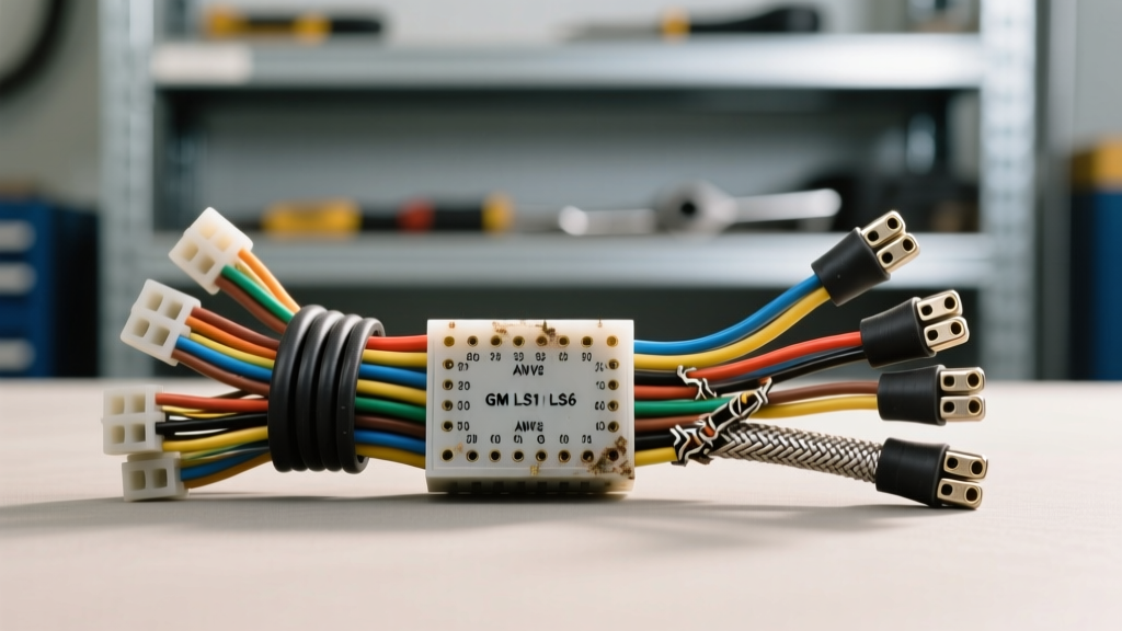
The Engineering Reality of OEM Harness Degradation
When executing a factory wiring harness replacement on late-model GM Gen III engines (LS1/LS6, 1997-2004), technicians must understand that the failure is rarely the copper conductor itself. The failure lies in the dielectric insulation and the polymer corrugated loom. Original equipment manufacturers utilize GXL or TXL cross-linked polyethylene (XLPE) insulation, which is rated for higher continuous temperatures than standard PVC. However, after two decades of thermal cycling between 180°F (ambient bay) and 250°F+ (near exhaust manifolds), the plasticizers migrate out of the insulation. This results in micro-fractures when the harness is flexed during removal.
According to the SAE J1128 Low Tension Primary Cable specifications, GXL wire features a thinner insulation wall (0.58mm nominal for 18 AWG) compared to SXL, allowing for tighter routing but demanding precise bending radius adherence during a factory wiring harness replacement to prevent internal copper work-hardening and subsequent strand breakage.
Diagnostic Triage: Partial Repair vs. Full Replacement
Before committing to a complete teardown, perform a dielectric integrity test. A full factory wiring harness replacement is mandated if you observe any of the following critical failure modes:
- Firewall Pass-Through Chafing: Inspect the main bulkhead connector (usually a 60-way or 80-way Delphi pack). If the drip loop was omitted or the grommet hardened and compressed, the harness rubs against the stamped steel firewall, compromising the 14 AWG ignition feeds.
- Injector Pigtail Delamination: The Multec 2 or Bosch EV6 injector connectors on the LS1 are subjected to extreme radiant heat. If the locking tang snaps or the silicone weather seal extrudes from the connector cavity, the entire pigtail must be replaced using OEM-style Metri-Pack 280 terminals.
- Capillary Action Corrosion: If a previous owner used dielectric grease improperly inside a sealed connector, or if the O2 sensor harness wicked moisture back to the ECU, the green verdigris (copper oxide) will travel under the wire insulation. Cut back 6 inches; if green persists, full replacement is the only reliable fix.
- Insulation Resistance Failure: Using a megohmmeter (Megger) at 50V DC, test the coil control circuits against chassis ground. Any reading below 20 Megohms indicates microscopic insulation breakdown that will cause intermittent misfires under high cylinder pressure.
LS1/LS6 Harness Architecture & ECU Pinout Specifications
The GM Gen III Powertrain Control Module (PCM) utilizes three primary connectors: C1 (Black, 80-way), C2 (Red, 80-way), and C3 (Gray, 40-way). When performing a factory wiring harness replacement, verifying pin migration and terminal seating in these blocks is critical. Below is a reference for high-failure-rate circuits during harness swaps.
| PCM Connector | Pin Number | Circuit Function | Wire Color | AWG Size | Connector Series |
|---|---|---|---|---|---|
| C1 (Black) | 20 | Injector 1 Control (Low Side) | Pink/Black | 18 | Metri-Pack 280 |
| C1 (Black) | 21 | Coil 1 Low Voltage Control | Pink | 18 | Metri-Pack 280 |
| C2 (Red) | 1 | MAF Sensor Signal | Yellow | 22 (Shielded) | Metri-Pack 150 |
| C2 (Red) | 19 | Vehicle Speed Sensor (VSS) High | Purple | 22 (Twisted) | Metri-Pack 150 |
| C3 (Gray) | 1 | Main PCM Ground 1 | Black/White | 14 | Ring Terminal / Metri-Pack 630 |
Note: Shielded wires (like the MAF signal) require the drain wire to be grounded exclusively at the PCM end to prevent ground loops and high-frequency alternator whine interference.
Execution Protocol: Terminal Crimping and Metallurgy
A successful factory wiring harness replacement hinges on terminal crimping. The Aptiv (formerly Delphi) Connection Systems Metri-Pack series relies on a specific bell-mouth crimp profile. Using a generic open-barrel crimp tool will result in insufficient wire pull-out strength and high millivolt drops under load.
The Anatomy of a Perfect OEM Crimp
- Conductor Crimp: The terminal wings must fold inward and bite into the copper strands without piercing them. The insulation must be visible at the front of the conductor crimp by exactly 0.5mm to 1.0mm.
- Insulation Crimp: The rear wings must encapsulate the GXL/TXL insulation tightly to provide strain relief, preventing vibration from transferring to the conductor crimp.
- Tooling: Use a ratcheting crimper calibrated for Delphi Metri-Pack 150/280 terminals (such as the S&G Tool Aid 38770). Never use solder inside the crimp barrel; solder wicks under the insulation, creating a rigid stress riser that will snap under engine vibration.
Splicing Protocols: Heat Shrink vs. Ultrasonic Welding
When integrating aftermarket sensors or repairing localized damage during a factory wiring harness replacement, the splice method dictates long-term reliability. Standard butt connectors are entirely unacceptable in engine bay environments due to vibration-induced fatigue.
For 18 AWG to 14 AWG circuits, use adhesive-lined polyolefin heat shrink splice sleeves with a brass crimp barrel. The inner layer of thermoplastic adhesive melts at 120°C, flowing into the wire strands and creating a watertight, environmental seal that prevents capillary corrosion. For high-frequency data lines (like the Class 2 Serial Data bus on the LS1), splices must be kept to an absolute minimum to prevent impedance mismatches that cause U-codes (communication network faults).
Grounding Topology and Millivolt Drop Validation
The most common cause of post-swap idle surges and erratic MAF readings is improper grounding. The LS1/LS6 utilizes a dedicated ground bus topology. During your factory wiring harness replacement, you must address the rear-of-block ground points.
The 14 AWG Black/White PCM grounds (C3 Pins 1, 40, and C1 Pin 1) must terminate at the right rear cylinder head. If you are using a reproduction harness, verify the terminal eyelet is tinned copper, not aluminum-clad copper (CCA). Clean the mating aluminum surface with a Scotch-Brite pad and apply a micro-layer of dielectric compound only to the exterior edges of the eyelet to prevent galvanic corrosion, never between the mating surfaces.
Load Testing the Replacement
Do not rely on a standard multimeter continuity beep. Perform a voltage drop test under load. With the engine running and the cooling fans commanded ON (drawing ~25 amps), measure the DC millivolt drop between the PCM ground pin breakout box and the alternator casing. A reading exceeding 50mV indicates excessive resistance in the ground path, requiring immediate harness remediation.
Post-Install Looming and Thermal Management
Finally, wrapping the new harness requires adherence to OEM routing standards. As detailed in the Haynes Chevrolet Camaro & Pontiac Firebird Repair Manual, the factory utilized high-temp fiberglass sleeving over the injector pigtails and specific nylon corrugated loom for the main trunk. When replacing the loom, use split-loom only where necessary for branch-outs, and seal all longitudinal splits with high-temp acrylic adhesive friction tape (e.g., Tesa 51036) to prevent the harness from "breathing" in engine oil vapors and moisture. Secure the harness every 8 inches using UV-resistant nylon zip ties or stainless steel P-clips, ensuring a minimum 1.5-inch clearance from exhaust manifolds to guarantee the longevity of your factory wiring harness replacement.