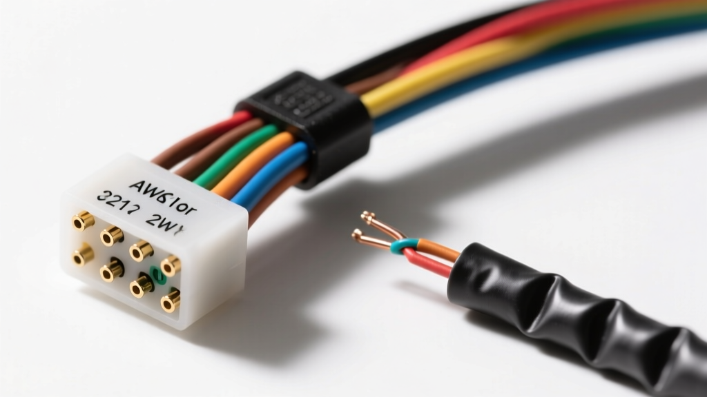
The Fragility of MAF Sensor Signals
The mass air flow (MAF) sensor is one of the most critical inputs for modern engine management systems. Whether you are building a custom mass air flow sensor wiring harness for an LS swap, repairing a chafed OEM pigtail, or extending wires for a custom intake plenum, the margin for error is virtually zero. Hot-wire and hot-film MAF sensors operate on a Wheatstone bridge circuit, maintaining a platinum wire or film at a precise temperature (typically 200°C above ambient intake air). The current required to maintain this temperature is converted into a low-voltage analog signal (usually 0.5V to 5.0V) or a frequency output.
Because these signals operate in the millivolt sensitivity range, a poorly executed wiring repair can introduce voltage drop, electromagnetic interference (EMI), or ground loops. A mere 0.1V fluctuation caused by a bad splice can trick the ECU into injecting significantly more or less fuel, resulting in severe hesitation, catalytic converter damage, or limp-mode triggers. Below are the most common mistakes and critical safety warnings when working with MAF sensor wiring.
Critical Safety Warnings Before You Cut
Before splicing into any engine management harness, you must adhere to strict electrical safety protocols to protect the ECU's sensitive internal driver circuits.
- Disconnect the Battery and Wait: Modern ECUs retain power in their capacitors and keep certain circuits 'awake' for up to 15 minutes after battery disconnect. Always pull the main battery ground and wait 20 minutes before cutting into the 5V reference or sensor ground wires to prevent backfeeding voltage spikes into the ECU's microprocessor.
- Beware of the Shared 5V Reference: The 5V reference wire on a MAF sensor (especially on GM and Ford applications where the Intake Air Temperature sensor is integrated) is often on a shared circuit with the MAP, TPS, and APP sensors. A short to ground during testing will instantly blow the internal 5V voltage regulator inside the ECU, requiring an expensive replacement or professional reflash/repair.
- Never Probe with Standard Test Lights: Never use an incandescent test light or a low-impedance multimeter on the MAF signal wire. The ECU's analog-to-digital (A/D) converter can be damaged by the current draw. Always use a high-impedance digital multimeter (10 Megohm minimum) or a digital storage oscilloscope (DSO) to read MAF waveforms.
Mistake #1: Using Unshielded Wire for the Signal Circuit
The most frequent failure in custom mass air flow sensor wiring harness builds is the use of standard, unshielded primary wire for the MAF signal circuit. The engine bay is a hostile EMI environment. High-energy ignition systems (like MSD or coil-near-plug setups), high-amp alternators, and electric cooling fan motors generate massive electromagnetic fields.
If your MAF signal wire acts as an antenna, it will absorb this 'noise,' causing the ECU to see erratic air flow spikes. According to Bosch Motorsport Engine Management guidelines, low-voltage analog sensor signals must be routed using shielded, twisted-pair cabling. The signal wire and its dedicated sensor ground should be twisted together (at least 2 to 3 twists per inch) to cancel out common-mode noise, and wrapped in a braided copper or Mylar shield.
Mistake #2: The Drain Wire Ground Loop
When using shielded cable for your MAF harness, the shield contains a bare copper 'drain wire' designed to route absorbed EMI to ground. A catastrophic mistake made by novice fabricators is grounding this drain wire at both the sensor connector and the ECU connector.
The Fix: The drain wire must be grounded only at the ECU harness plug (spliced into a dedicated ECU sensor ground or shield drain pin) and left completely floating (capped with heat shrink) at the MAF sensor end. Grounding both ends creates a ground loop. Because the engine block and the ECU chassis often sit at slightly different electrical potentials, current will flow through the shield, turning your EMI protection into an active interference antenna that injects alternator whine directly into the MAF signal.
Mistake #3: T-Tapping the 5V Reference or Signal Wires
Using 'Scotch-Lok' T-taps or piercing clamps to add a datalogger wire to the MAF signal or 5V reference circuit is a guaranteed way to cause long-term reliability issues. These connectors rely on a small metal blade piercing the insulation to make contact with the copper strands.
Over time, engine vibration, thermal cycling, and moisture ingress cause the pierced insulation to degrade and the copper to oxidize. This introduces micro-resistance into the circuit. On a 5V reference circuit shared with other sensors, this resistance creates a voltage drop. If the ECU's 5V rail drops to 4.8V at the MAF sensor, the ECU will miscalculate the air density, leading to part-throttle surging. Always use a proper parallel splice, soldered and sealed, or route a dedicated secondary wire back to a datalogging ECU pin if available.
Mistake #4: Ignoring Wire Gauge (AWG) and Connector Specifications
Using wire that is too thick or too thin will cause physical stress on the sensor pins or create unwanted resistance. Adhering to the SAE J1128 standard for low-tension primary cable ensures you are using wire rated for under-hood temperatures and chemical exposure.
| Circuit Type | Recommended AWG | Wire Type / Insulation | Notes & Requirements |
|---|---|---|---|
| MAF Signal (Analog/Freq) | 20 AWG | Shielded, Twisted Pair (Tefzel/XLPE) | Must use shielded cable. High-temp insulation required. |
| 12V Ignition / Power Feed | 18 AWG | Cross-Linked Polyethylene (XLPE) | Standard primary wire. Route away from exhaust manifolds. |
| MAF Low Reference (Ground) | 20 AWG | Shielded, Twisted Pair (with Signal) | Must return directly to ECU. Do NOT ground to chassis. |
| IAT Signal (If Integrated) | 20 AWG | Standard Primary (TXL/GXL) | Thermistor circuit. Keep away from radiant heat sources. |
Mistake #5: Universal Pigtail Pinout Assumptions
When replacing a melted or brittle OEM connector, many mechanics grab a 'universal' MAF pigtail from an auto parts store and wire it pin-for-pin based on the old connector's physical layout. This is highly dangerous, as physical pin locations do not dictate electrical function across different manufacturers. For example, a Bosch 5-pin Jetronic connector and a GM Delphi Metri-Pack 150 5-pin connector have completely different internal wiring architectures.
Common 5-Pin MAF/IAT Combo Pinout Comparison
| Pin Function | GM LS/LT (Delphi 5-Pin) | Typical Bosch (Jetronic 5-Pin) |
|---|---|---|
| 12V Switched Power | Pin E (Pink Wire) | Pin 3 (Red/Black Wire) |
| MAF Signal to ECU | Pin C (Yellow Wire) | Pin 5 (Blue/Yellow Wire) |
| MAF Low Ref (Sensor Grd) | Pin D (Black/White Wire) | Pin 4 (Brown Wire) |
| IAT Signal (5V Ref) | Pin A (Dark Blue/Yellow) | Pin 1 (Green/White Wire) |
| IAT Low Ref (Sensor Grd) | Pin B (Black Wire) | Pin 2 (Brown/White Wire) |
Always verify pinouts using Delphi Technologies wiring schemas or factory service manuals before applying power. Swapping the 12V power feed into the MAF Signal pin will instantly fry the ECU's internal A/D converter.
Proper Splicing and Sealing Techniques
If you must repair a MAF harness, avoid standard electrical tape and cheap vinyl heat shrink. The under-hood environment exposes wiring to oil, unburnt hydrocarbons, and extreme thermal cycling, which will melt standard adhesive and cause capillary action to wick moisture into the copper strands, leading to green corrosion (copper oxide) that increases resistance.
- Strip and Stagger: Strip the wires and stagger the splice points so the bulky solder joints do not sit directly next to each other, maintaining harness flexibility.
- Solder and Flux: Use rosin-core solder. Never use acid-core plumbing solder, which will eat through the fine 20 AWG stranded wire over time.
- Dual-Wall Heat Shrink: Use marine-grade, dual-wall polyolefin heat shrink with an inner lining of thermoplastic adhesive. When heated, the inner adhesive melts and seals the splice completely from moisture and chemicals, while the outer wall provides abrasion resistance.
- Re-wrap the Harness: Finish the repair by wrapping the harness in Tesa cloth friction tape or split nylon braided loom to protect against vibration and abrasion against the intake tube.
Summary Checklist for MAF Harness Fabrication
Before starting your engine after modifying or repairing a mass air flow sensor wiring harness, run through this final checklist:
- Verify all wire gauges match OEM specifications (typically 18-20 AWG).
- Confirm the shield drain wire is grounded ONLY at the ECU end.
- Test continuity from the sensor plug to the ECU plug (should be less than 0.5 ohms).
- Test for shorts to chassis ground on the MAF Signal and 5V Reference wires (must read infinite resistance / OL).
- Ensure no T-taps or Scotch-Loks were used on low-voltage reference circuits.
By respecting the delicate nature of analog sensor signals and adhering to strict automotive wiring standards, you ensure your engine management system receives clean, accurate data, resulting in optimal drivability and performance.