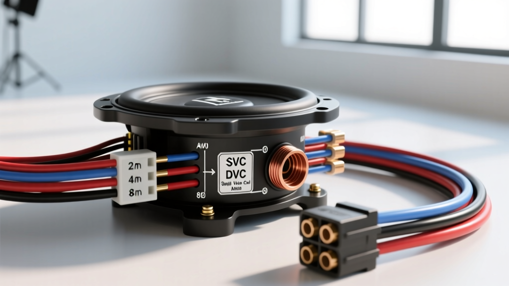
The Impedance Bottleneck: Selecting Your Subwoofer Configuration
When building a high-output car audio system, selecting the right subwoofer goes far beyond matching RMS wattage ratings. The true bottleneck in system design is impedance matching, which dictates exactly which sub wiring diagram you must follow to extract maximum power without triggering your amplifier's protection circuitry. Choosing between Single Voice Coil (SVC) and Dual Voice Coil (DVC) architectures fundamentally alters your wiring flexibility, final ohm load, and the physical routing of your speaker wire.
This selection guide breaks down the electrical characteristics of SVC and DVC subwoofers, provides real-world impedance scenarios, and details the exact American Wire Gauge (AWG) and terminal specifications required for a reliable, competition-grade installation.
SVC vs. DVC: Core Architectural Differences
A voice coil is the electromagnetic engine of your subwoofer. The number of coils and their individual resistance (measured in ohms) determine how the amplifier perceives the electrical load. Before you pull a specific sub wiring diagram, you must understand the physical limitations of your chosen driver.
| Feature | Single Voice Coil (SVC) | Dual Voice Coil (DVC) |
|---|---|---|
| Terminal Count | 2 (One Positive, One Negative) | 4 (Two Positive, Two Negative) |
| Wiring Flexibility | Low (Fixed Impedance) | High (Series, Parallel, or Series-Parallel) |
| Typical Configurations | 2-Ohm or 4-Ohm | 2-Ohm + 2-Ohm, or 4-Ohm + 4-Ohm |
| Best Application | Budget builds, exact amp matching | Multi-sub arrays, max power extraction |
| Wire Routing Complexity | Simple (Direct to amp) | Moderate (Requires jumper wires or series routing) |
According to the Consumer Technology Association (CTA) mobile audio standards, DVC subwoofers are the industry preference for high-power systems because they allow the installer to manipulate the final load to match the amplifier's lowest stable impedance threshold.
Decoding the Ohm Load: Amplifier Stability Thresholds
Every car audio amplifier has a minimum stable impedance rating. Pushing an amplifier below this threshold causes the output stage to draw excessive current, leading to thermal runaway and immediate shutdown. Conversely, wiring a load higher than necessary leaves wattage on the table.
- 4-Ohm Stable Amps: Standard for most factory-integrated or compact Class D amplifiers.
- 2-Ohm Stable Amps: Common in mid-tier monoblock amplifiers; requires parallel wiring of DVC 4-ohm subs.
- 1-Ohm Stable Amps: Reserved for high-current, premium Class D monoblocks with massive power supplies and upgraded alternators.
Scenario A: Single DVC 4-Ohm Subwoofer to a 2-Ohm Stable Amp
This is the most common sub wiring diagram for daily-driven vehicles. You have one subwoofer with two 4-ohm coils, and an amplifier rated for 500W RMS at 2 ohms.
The Wiring Strategy (Parallel):
- Connect a jumper wire from the positive terminal of Coil 1 to the positive terminal of Coil 2.
- Connect a jumper wire from the negative terminal of Coil 1 to the negative terminal of Coil 2.
- Run your main speaker wire from the remaining open positive terminal to the amplifier's positive output.
- Run the main speaker wire from the remaining open negative terminal to the amplifier's negative output.
Impedance Math: In a parallel circuit, the formula is R_total = (R1 x R2) / (R1 + R2). Therefore, (4 x 4) / (4 + 4) = 16 / 8 = 2 Ohms. Your amplifier will now output its maximum rated 2-ohm wattage safely.
Scenario B: Dual DVC 2-Ohm Subwoofers to a 1-Ohm Stable Amp
For SPL (Sound Pressure Level) builds utilizing two subwoofers, each with dual 2-ohm coils, you need a series-parallel sub wiring diagram to achieve a 1-ohm final load.
The Wiring Strategy (Series-Parallel):
- Series on the Subwoofers: On Sub 1, connect a jumper from the negative terminal of Coil 1 to the positive terminal of Coil 2. Repeat this exact process on Sub 2. This makes each individual subwoofer present a 4-ohm load (2 + 2 = 4).
- Parallel to the Amplifier: Connect the remaining positive terminal of Sub 1 to the remaining positive terminal of Sub 2, then run a single wire to the amplifier's positive terminal.
- Connect the remaining negative terminal of Sub 1 to the remaining negative terminal of Sub 2, then run a single wire to the amplifier's negative terminal.
Impedance Math: The two 4-ohm subwoofers are now wired in parallel at the amplifier. (4 x 4) / (4 + 4) = 1 Ohm. This perfectly matches a 1-ohm stable monoblock, yielding maximum current delivery.
Wire Gauge, Terminals, and SAE Standards
Selecting the correct sub wiring diagram is only half the battle; executing it with the proper materials prevents voltage drop and thermal compression. The SAE J1128 Low Tension Primary Cable Standard outlines the strict requirements for DC wiring in automotive environments, emphasizing the dangers of undersized conductors.
OFC vs. CCA: The Hidden Resistance Trap
Always select Oxygen-Free Copper (OFC) for your speaker and power wire. Copper-Clad Aluminum (CCA) wire has approximately 30% higher resistance than OFC. If you must use CCA due to budget constraints, you must step up one full AWG size (e.g., use 10 AWG CCA instead of 12 AWG OFC) to maintain the same current-carrying capacity.
Terminal Specifications and Torque
Never wrap bare wire around binding posts or shove frayed strands into amplifier set-screw terminals. This creates high-resistance points that generate heat and melt terminal blocks.
- Amplifier Power/Ground: Use closed-ring terminals (typically #8 or #10 stud size). Crimp using a hex-compression crimper, then seal with 3:1 adhesive-lined marine heat shrink to prevent galvanic corrosion.
- Subwoofer Push Terminals: Use spade connectors or properly tinned bare wire. If using set-screws on the subwoofer basket, torque to exactly 1.5 Nm. Over-torquing will strip the soft brass set-screw against the hardened copper wire, leading to a catastrophic failure under high-excursion bass hits.
- Speaker Wire Gauge: For runs under 15 feet at 500W RMS, 12 AWG OFC speaker wire is the minimum standard. For runs exceeding 15 feet or exceeding 800W RMS, step up to 10 AWG to minimize inductance and preserve the amplifier's damping factor.
Common Wiring Failure Modes & Troubleshooting
Even with the correct sub wiring diagram, physical installation errors can mimic impedance faults. Use this decision tree to diagnose protection-mode triggers:
Symptom: Amplifier goes into Protect Mode immediately upon heavy bass transients.
- Cause 1: Voltage Drop. The 12V power wire is too thin (e.g., 8 AWG on a 1000W amp). When the subwoofer demands sudden current, system voltage drops below 11V, triggering the amp's undervoltage protection. Fix: Upgrade to 4 AWG or 1/0 AWG OFC power wire.
- Cause 2: Clipping / Impedance Mismatch. The subwoofer voice coil is overheating from a clipped signal, causing its resistance to rise (thermal compression), or a stray strand of copper is shorting the terminal block. Fix: Set gain with an oscilloscope, inspect terminal blocks for stray wire strands, and verify ohm load with a multimeter while disconnected from the amp.
Symptom: Output is exceptionally weak and lacks impact.
- Cause: Out-of-Phase Wiring. In a multi-sub DVC setup, one subwoofer was wired with reversed polarity (positive to negative). The subs are physically fighting each other, canceling out low-frequency waves. Fix: Perform a 9V battery pop test on each subwoofer individually to verify cone excursion direction before finalizing the sub wiring diagram connections.
Final Selection Checklist
Before purchasing your subwoofers and amplifier, complete this verification loop:
- Verify the amplifier's certified RMS wattage at the target impedance (refer to the CTA-2006 compliant birth sheet, not the manual's peak ratings).
- Calculate the final ohm load using the appropriate series or parallel sub wiring diagram.
- Confirm the vehicle's electrical system (alternator output and battery reserve capacity) can sustain the current draw. A 1-ohm setup pulling 100A+ requires a high-output alternator and a dedicated secondary battery.
- Map your physical wire routing, ensuring speaker wires are kept at least 12 inches away from RCA signal cables to prevent electromagnetic interference (EMI).
By matching the voice coil architecture to your amplifier's stable impedance threshold, you ensure that your system operates efficiently, safely, and at maximum acoustic output. For further competition-level installation guidelines, refer to the International Auto Sound Challenge Association (IASCA) rulebooks regarding wire management and safety standards.