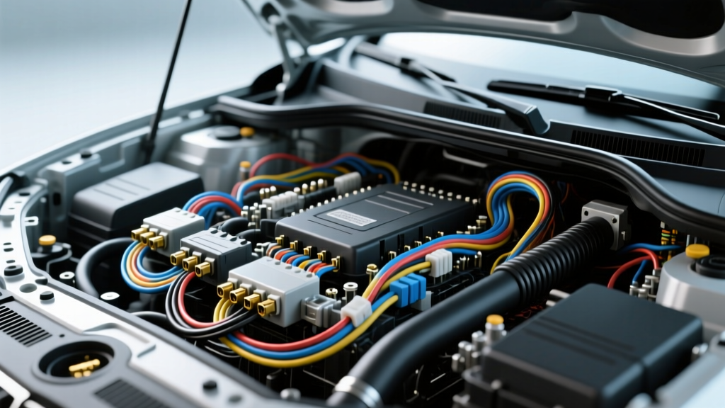
Understanding the High Tech Auto Electric Architecture
Modern vehicles have evolved from simple point-to-point 12-volt circuits into complex, multiplexed networks. When diagnosing a high tech auto electric system, technicians must shift their mindset from measuring simple continuity to analyzing digital data streams. The Controller Area Network (CAN) bus is the backbone of this architecture, allowing dozens of microprocessors to communicate over a shared pair of wires. According to the CAN in Automation (CiA) consortium, high-speed CAN (ISO 11898-2) operates at up to 1 Mbps, making it highly sensitive to wiring faults, impedance mismatches, and electromagnetic interference (EMI).
Troubleshooting these networks requires a systematic, step-by-step flow. A single chafed wire or corroded pin can corrupt the differential voltage, causing cascading module failures, limp-mode activations, and a dash full of warning lights. This guide provides a definitive diagnostic decision tree for resolving high-speed CAN bus faults, complete with specific pin configurations, AWG ratings, and oscilloscope setups.
Step 1: Preliminary OBD2 Port Voltage Check
Before tearing into dash panels or tracing harnesses through the firewall, start at the Data Link Connector (DLC). The OBD2 port provides direct access to the high-speed CAN network. Set your digital multimeter (DMM) to DC Volts and use a known good ground (Pin 4 or 5) as your reference.
OBD2 Pinout Reference:
- Pin 6: CAN-H (High) - Typically White, Yellow, or Orange/White wire.
- Pin 14: CAN-L (Low) - Typically Green, Black, or Orange/Brown wire.
- Pin 4: Chassis Ground.
- Pin 5: Signal Ground.
With the ignition ON and the engine OFF (KOEO), back-probe Pin 6 and Pin 14. Because the CAN bus transmits data in rapid bursts, a standard DMM will display an average voltage. You should read approximately 2.6V to 3.5V on CAN-H and 1.5V to 2.4V on CAN-L. If you read 0V on both, the network is completely down or shorted to ground. If you read 12V, the CAN-H wire is shorted to battery positive. If both pins read exactly 2.5V and do not fluctuate, the bus may be stuck in a recessive state, indicating a failed module or a severed data line.
Step 2: Termination Resistance Verification
If voltage checks are inconclusive or point to a network crash, the next step in our troubleshooting flow is to verify the physical layer's termination. The high-speed CAN bus requires a 120-ohm termination resistor at each end of the network to prevent signal reflection. Because these two resistors are in parallel, the total resistance measured across the bus should be exactly 60 ohms.
Testing Procedure:
- Turn the ignition OFF and remove the key.
- Disconnect the vehicle battery to prevent back-feeding voltage into your multimeter, which can damage the DMM or blow its internal fuse.
- Set your DMM to Ohms (Ω).
- Measure the resistance between OBD2 Pin 6 (CAN-H) and Pin 14 (CAN-L).
Diagnostic Outcomes:
- ~60 Ω: Termination is perfect. The physical wiring backbone is intact.
- ~120 Ω: One termination resistor is missing, open, or a main trunk wire is severed, isolating one end of the bus.
- ~0 Ω to 10 Ω: CAN-H and CAN-L are shorted together. This will completely crash the network.
- OL (Over Limit): Both resistors are missing, or the DLC is disconnected from the main harness.
Step 3: Signal Integrity and Oscilloscope Analysis
A multimeter only tells half the story. To truly diagnose a high tech auto electric communication fault, you must view the waveform. The National Instruments CAN bus guide emphasizes that differential signaling relies on the voltage difference between the two wires, not their voltage to ground.
Oscilloscope Setup:
- Channel A (CAN-H): 2V/div, Offset -2V.
- Channel B (CAN-L): 2V/div, Offset -2V.
- Timebase: 10 µs/div to 20 µs/div (captures the 500 kbps bit rate perfectly).
- Trigger: Edge trigger on Channel A, rising edge, ~3.0V.
Connect your probes to OBD2 Pins 6 and 14. A healthy CAN bus will display a dominant state where CAN-H spikes up to ~3.5V and CAN-L drops to ~1.5V simultaneously, creating a differential voltage of 2.0V. The recessive state shows both lines returning to ~2.5V (0V differential). Look for 'ringing' (oscillations at the top and bottom of the square waves), which indicates poor termination or untwisted wire repairs. If the dominant voltage only reaches 2.8V, you have excessive voltage drop, usually caused by corroded splice joints or undersized replacement wiring.
Step 4: Module Isolation and Dropout Testing
When the CAN bus is shorted to ground or voltage, the entire network crashes. To find the culprit, use the module isolation method. Consult the factory wiring diagram to identify all modules on the affected CAN bus (e.g., PCM, TCM, ABS, BCM, SAS).
With the battery disconnected and your DMM measuring resistance or continuity to ground, systematically unplug each module or pull its designated CAN-bus fuses one by one. When you disconnect the faulty module, the short to ground will disappear, and the network resistance will return to normal. Common failure points include water intrusion in the ABS module connector, chafed wiring harnesses near the steering column clock spring, and internal PCM failures where the CAN transceiver chip burns out and shorts the bus.
High Tech Auto Electric CAN Bus Specifications
| Parameter | Specification / Value | Diagnostic Notes |
|---|---|---|
| CAN-H Recessive Voltage | ~2.5V | Idle state, no data transmission. |
| CAN-H Dominant Voltage | ~3.5V | Active data bit (Logic 0). |
| CAN-L Recessive Voltage | ~2.5V | Idle state, no data transmission. |
| CAN-L Dominant Voltage | ~1.5V | Active data bit (Logic 0). |
| Total Bus Resistance | 60 Ω (± 5 Ω) | Two 120 Ω resistors in parallel. |
| Standard Wire Gauge | 20 AWG (0.5 mm²) | Unshielded Twisted Pair (UTP). |
| Twist Rate | 1 twist per 1 inch (approx) | Crucial for EMI cancellation. |
Real-World Failure Modes and Wiring Repairs
When repairing a high-speed CAN bus, standard 12-volt repair practices are insufficient. The SAE J1939 standards for heavy-duty and high-speed automotive networks dictate strict physical layer requirements to maintain signal integrity.
Prohibited Repair Methods:
- Twist-on wire connectors (Wire Nuts): These introduce severe impedance mismatches and will cause signal reflection.
- Standard Electrical Tape: Fails to keep moisture out and degrades under hood temperatures, leading to corrosion.
- Untwisted Splices: Failing to maintain the twisted pair geometry destroys the common-mode noise rejection, making the bus susceptible to alternator whine and ignition EMI.
Approved Repair Procedure:
- Cut out the damaged section of the 20 AWG CAN wire.
- Source factory-spec Unshielded Twisted Pair (UTP) cable. If unavailable, use high-quality 20 AWG automotive cross-linked polyethylene (XLPE) wire and twist it tightly (at least one twist per inch).
- Strip exactly 5mm to 6mm of insulation. Do not nick the copper strands.
- Crimp using an open-barrel terminal (e.g., TE Connectivity MQS or Deutsch DT series) with a precision ratcheting crimper.
- Solder the connection only if required by the OEM, but note that excessive solder wicking can create a stiff 'club' in the wire that breaks under vibration. High-quality crimps are generally preferred.
- Seal the repair using a dual-wall, polyamide-lined heat shrink tube. Apply heat evenly until the adhesive purges from both ends, ensuring a completely waterproof seal.
By following this structured troubleshooting flow, you can confidently isolate, diagnose, and repair faults within any high tech auto electric CAN bus network, restoring vehicle communication and eliminating phantom electrical gremlins.