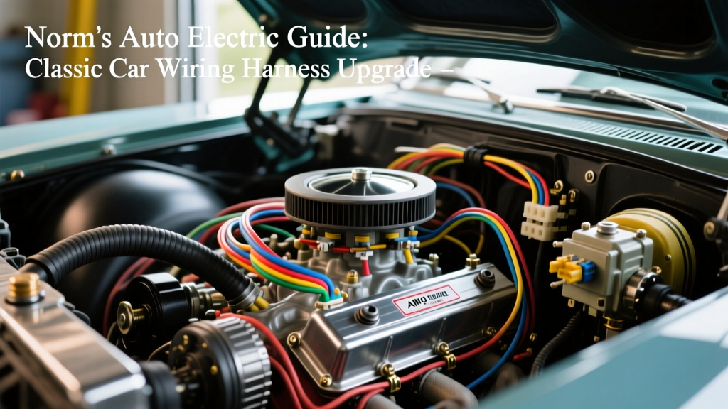
The 'Norm's Auto Electric' Philosophy for Modernizing Classics
When veteran hot rod builders and classic car restorers talk about bulletproof electrical systems, they often reference the 'Norm's Auto Electric' standard. While Norm's represents the archetype of the master-level, no-nonsense local auto electrical shop, the methodology is universal: prioritize voltage stability, eliminate archaic glass-fuse bottlenecks, and use aerospace-grade routing techniques. Upgrading a classic muscle car or vintage truck from its original 40-amp, externally regulated electrical system to a modern, high-output architecture requires more than just swapping parts. It requires a complete reimagining of the vehicle's copper backbone.
This upgrade and modification guide walks you through executing a professional-grade electrical overhaul inspired by top-tier auto electric shops. We will cover high-output alternator conversions, high-torque starter relay upgrades, centralized blade-fuse distribution, and zero-voltage-drop grounding protocols.
Phase 1: High-Output Alternator & Charging System Overhaul
Classic vehicles originally equipped with 10SI or early 12SI alternators typically max out at 63 to 94 amps, which is woefully inadequate for modern modifications like electric fuel pumps, EFI systems, and high-draw cooling fans. The industry-standard upgrade is the GM CS130D or Denso-style internally regulated alternator, capable of 130A to 170A at idle.
However, simply bolting on a 1-wire alternator often leads to undercharging at low RPMs. The 'Norm's Auto Electric' approach mandates a true 3-wire setup to ensure the alternator's internal voltage regulator accurately reads the system's actual voltage demand.
GM CS130D 4-Pin Connector Wiring Protocol
The CS130D utilizes a 4-pin connector, though typically only three terminals are populated for standard street applications. According to Mad Electrical's alternator technical guidelines, wiring the sense circuit correctly is the difference between a 13.8V system and a 14.4V system.
| Terminal | Label | Function | Wire Gauge & Color | Routing Destination |
|---|---|---|---|---|
| P | Phase | Tachometer signal (AC voltage) | 18 AWG (White) | EFI ECU or Tachometer (if required) |
| L | Lamp | Indicator lamp / Excitation | 16 AWG (Brown) | Ignition switch via 194 bulb or 500-ohm resistor |
| I | Ignition | Optional 12V wake-up signal | 16 AWG (Pink) | Switched 12V source (often jumpered to L) |
| S | Sense | Battery voltage feedback | 14 AWG (Red) | Main battery positive or main distribution stud |
Critical Modification: The 'S' (Sense) wire must never be looped directly back to the alternator's output stud. It must be routed to the main battery positive terminal or the primary power distribution block. This allows the regulator to compensate for voltage drop across the main charge cable.
For the main charge wire, upgrade the factory 10 AWG wire to 4 AWG GXL (Cross-Linked Polyethylene) wire. GXL wire features a thinner insulation wall than standard PVC, allowing for better heat dissipation and flexibility in tight engine bays, compliant with SAE J1128 Low Tension Primary Cable standards. Always protect this main feed with a 150-Amp Marine-rated Mega Fuse mounted within 18 inches of the battery positive terminal.
Phase 2: High-Torque Starter & Solenoid Relay Upgrade
A common failure mode in modified classic V8s is the 'hot start' issue. Heat soak from exhaust headers increases the electrical resistance of the factory starter solenoid trigger wire, dropping the voltage below the 9.5V threshold required to engage the starter bendix. The solution is upgrading to a gear-reduction mini starter and installing a dedicated solenoid relay.
Wiring the Bosch-Style Starter Relay
By using a standard 40A Bosch-style relay (often found in 5-pin configurations, utilizing 4 pins), you bypass the aging ignition switch wiring entirely for the high-current starter trigger.
- Terminal 30 (Power In): Connect to the battery positive via a dedicated 10 AWG red wire, protected by a 20A ATO inline fuse.
- Terminal 87 (Power Out): Connect to the 'S' (Start) terminal on the mini-starter solenoid using 10 AWG red wire.
- Terminal 86 (Trigger In): Connect to the original factory starter trigger wire (usually Purple or Yellow, 14 AWG) coming from the ignition switch neutral safety circuit.
- Terminal 85 (Ground): Connect to a clean, bare-metal chassis ground using 14 AWG black wire.
This modification ensures the starter solenoid receives a full 12.5V+ regardless of engine bay temperatures or ignition switch wear. For the main battery-to-starter cable, use 2 AWG stranded copper battery cable with adhesive-lined marine heat shrink on the ring terminals to prevent acid and moisture wicking.
Phase 3: Centralized Blade Fuse Distribution
Architecting a custom harness means abandoning the factory glass-fuse panel. Glass fuses suffer from high contact resistance, oxidation, and poor vibration tolerance. The modern standard requires a centralized power distribution module utilizing ATO/ATC blade fuses and integrated Bosch-style relays for high-draw circuits.
Circuit Mapping & AWG Specification Chart
When building your custom harness, wire sizing must be calculated based on the maximum continuous draw of the circuit, not just the fuse rating. The following table outlines the 'Norm's' standard for a typical modified V8 street machine.
| Circuit | Max Draw | Fuse Rating | Wire Gauge (AWG) | Wire Color Code |
|---|---|---|---|---|
| Electric Fuel Pump (In-Tank) | 12A | 15A ATO | 12 AWG | Blue w/ White Stripe |
| EFI ECU & Sensors | 8A | 10A ATO | 14 AWG | Orange |
| Headlights (Halogen H4) | 18A (pair) | 20A ATO | 12 AWG | Red w/ Black Stripe |
| Dual Electric Cooling Fans | 28A | 30A ATO | 10 AWG | Green |
| Ignition System (MSD/Coil) | 10A | 15A ATO | 12 AWG | Pink |
| Wiper Motor (Upgraded) | 14A | 20A ATO | 12 AWG | Grey |
Note: All high-draw circuits (Fans, Fuel Pump, Headlights) must be triggered via relays located in the central distribution block, keeping high-current wiring out of the cabin and dashboard.
Phase 4: The Zero-Voltage-Drop Grounding Protocol
The most overlooked aspect of any modification project is the ground return path. A 130A alternator is useless if the ground path cannot handle the current. Professional auto electric shops utilize a 'Star Ground' or 'Braided Strap' methodology to ensure continuity.
- Engine to Chassis: Use a minimum 2 AWG braided copper ground strap connecting the lower engine block bolt to the frame rail. Braided straps resist the high-frequency vibration of the V8 engine better than solid wire, preventing internal strand fatigue and breakage.
- Chassis to Body: Connect the frame rail to the firewall and cabin tub using 4 AWG braided straps.
- Surface Preparation: Never ground to painted metal, powder coat, or rust. Use a wire wheel or sanding disc to expose bare, shiny steel at every grounding point.
- Hardware: Use zinc-plated or stainless steel bolts paired with internal star washers. The star washer bites through microscopic surface oxidation to guarantee a low-resistance electrical connection, while the bolt head maintains clamping force.
Testing and Validation Standards
Once the harness is routed, loomed, and secured with stainless steel adel clamps (never zip-ties near exhaust), the system must be validated. Perform a voltage drop test across the main charge cable with the engine running at 2,000 RPM and all electrical loads (fans, headlights, fuel pump) activated. A reading of more than 0.2V across the positive cable, or more than 0.1V across the ground straps, indicates poor crimps or inadequate wire gauge.
By adhering to these rigorous modification standards, you elevate your project from a backyard wiring job to a professional, reliable machine that honors the legendary auto electric craftsmen who paved the way. For further reading on harness routing and terminal crimping standards, refer to the technical manuals provided by Painless Performance Products, which offer excellent visual guides for classic car chassis integration.