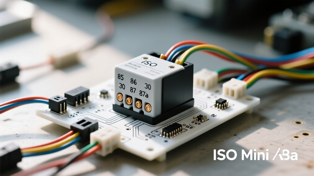
Understanding the Automotive Relay
Relays are the unsung heroes of modern automotive electrical systems. They act as heavy-duty remote-controlled switches, allowing a low-current circuit (like a dashboard switch or an ECU signal) to control a high-current load (like headlights, fuel pumps, or cooling fans). When a relay fails, the component it powers simply stops working, often leaving drivers stranded or dealing with intermittent electrical gremlins.
For beginners and seasoned technicians alike, knowing how to check a car relay with a multimeter is a fundamental diagnostic skill. Rather than blindly swapping parts, a systematic multimeter test isolates the failure to either the relay's internal electromagnetic coil, its high-current switching contacts, or the vehicle's wiring harness. According to the diagnostic standards outlined by AA1Car Automotive Electrical, over 70% of perceived "component failures" in high-draw circuits are actually relay or socket issues.
Anatomy of the ISO Mini Relay
The most ubiquitous relay found in vehicles ranging from a 2004 Honda Civic to a 2023 Ford F-150 is the standard ISO mini relay. Governed by the ISO 7588-1:2012 standard, these relays feature standardized pin numbering and terminal sizes, making them universally testable.
Standard ISO mini relays utilize 6.3mm (1/4-inch) spade terminals, while smaller "micro" relays use 4.8mm spades. Below is the definitive pinout reference for a standard 4-pin and 5-pin ISO relay:
| Pin Number | Function | Typical Wire Gauge (AWG) | Common OEM Wire Colors | Circuit Type |
|---|---|---|---|---|
| 30 | Common (Power In) | 12 AWG to 10 AWG | Red, Black/Yellow, Heavy White | High-Current Load |
| 85 | Coil Ground | 18 AWG | Black, Black/White | Low-Current Control |
| 86 | Coil Power (Switched) | 18 AWG | Pink, White, Green, Light Blue | Low-Current Control |
| 87 | Normally Open (Power Out) | 12 AWG to 10 AWG | Varies by load (e.g., Green for headlights) | High-Current Load |
| 87a | Normally Closed (5-Pin Only) | 12 AWG | Varies (Used for dual-function circuits) | High-Current Load |
Tools Required for Relay Diagnostics
To properly test a relay, you will need:
- Digital Multimeter (DMM): Must have Ohms (Ω), Continuity (audible beep), and DC Voltage (V) settings.
- 12V Power Source: A spare vehicle battery or a 12V DC power supply for bench testing.
- Jumper Wires: 14 AWG fused jumper wires with female spade connectors to interface with the relay pins.
- Backprobe Pins or T-Pins: For testing the vehicle's relay socket without damaging the female terminals.
Phase 1: Testing the Electromagnetic Coil (Control Circuit)
The control circuit consists of Pins 85 and 86. When 12 volts is applied across these pins, an electromagnetic field is generated, pulling the internal switch closed. We test this by measuring the resistance of the copper windings inside the coil.
Step-by-Step Coil Resistance Test
- Remove the relay from the vehicle's fuse box.
- Set your multimeter to the Ohms (Ω) setting. If your meter is auto-ranging, ensure it is not in the Megohm range.
- Place one probe on Pin 85 and the other on Pin 86. Polarity does not matter for standard resistance testing.
- Interpret the Reading:
- Normal: A healthy 12V automotive relay coil will typically read between 50 and 120 ohms.
- Open Circuit (OL): If the meter reads "OL" or infinity, the internal copper wire is broken. The relay is dead and must be replaced.
- Short Circuit (Near 0 Ω): If the reading is below 10 ohms, the windings are shorted together. This will blow the control circuit fuse in the vehicle.
Expert Note on Flyback Diodes: Many modern OEM relays contain an internal suppression diode (flyback diode) across Pins 85 and 86 to prevent voltage spikes from damaging the ECU when the relay de-energizes. If your relay has a diode, testing with the multimeter's "Diode Test" mode will show ~0.6V in one direction and "OL" when you swap the probes. This is normal and indicates a healthy diode.
Phase 2: Testing the High-Current Load Circuit (Switched Contacts)
The load circuit handles the heavy amperage (often 20A to 40A) and consists of Pins 30 and 87. These contacts must remain completely open when the relay is at rest, and form a near-perfect connection when energized.
Continuity and Contact Resistance Test
- With the relay completely disconnected from power and the multimeter still in Ohms/Continuity mode, place your probes on Pin 30 and Pin 87.
- At Rest (Unpowered): The meter should read "OL" (Open Loop) with no continuity beep. If it beeps or shows low resistance, the internal contacts are welded together. The relay is faulty.
- Bench Energizing: Using your jumper wires, apply 12V from your battery to Pin 86 and Ground to Pin 85. You should hear a distinct, sharp "click".
- Under Power (Energized): While maintaining the 12V trigger, check the resistance between Pin 30 and Pin 87 again. The reading should drop to less than 0.5 ohms (ideally under 0.05 ohms). The continuity alarm should sound loudly.
If the relay clicks but the resistance remains high (e.g., 2 ohms or more) or fluctuates, the internal carbon contacts are pitted, burned, or corroded. This high resistance will cause a severe voltage drop, resulting in dim headlights or a slow-cranking fuel pump, eventually melting the plastic relay socket.
Phase 3: Testing the Vehicle Harness Socket
A brand-new relay will not function if the vehicle's wiring harness is faulty. If your relay tests perfectly on the bench, you must verify the socket.
- Set the multimeter to DC Volts (20V range).
- Reconnect the vehicle battery and turn the ignition to the "ON" position (or activate the specific circuit, like turning on the headlights).
- Insert your black (ground) probe into a known good chassis ground or the negative battery terminal.
- Backprobe the relay socket's Pin 30 cavity with the red probe. You should read full battery voltage (12.2V - 12.6V). If you read 0V, you have a blown main fuse or a broken 10 AWG wire between the battery and the fuse box.
- Backprobe the Pin 86 cavity. You should also read 12V (or ground, depending on whether the OEM switches the power or the ground side of the coil). If Pin 86 is the ground-side switch, move your red probe to Pin 85 and backprobe Pin 86 with the black probe to verify the ground path.
- Check the Load Output Wire (Pin 87 cavity) for continuity to the actual component (e.g., the fuel pump connector). Set the meter to Ohms, place one probe in the Pin 87 cavity and the other at the component's power terminal. It should read less than 1.0 ohms.
Troubleshooting Decision Tree: Symptom to Resolution
Use this quick-reference table to diagnose real-world electrical symptoms based on your multimeter findings.
| Vehicle Symptom | Multimeter Finding | Root Cause | Resolution |
|---|---|---|---|
| Component dead, no relay click | Pins 85/86 read "OL" (Infinite) | Internal coil wire snapped | Replace relay |
| Component dead, relay clicks loudly | Pins 30/87 read > 2.0 Ω when energized | Carbon buildup / pitted contacts | Replace relay, inspect socket for heat damage |
| Component runs constantly, key off | Pins 30/87 beep continuity when unpowered | Contacts welded shut from arcing | Replace relay, check for shorted load component |
| Blown control circuit fuse instantly | Pins 85/86 read < 5 Ω | Shorted coil windings | Replace relay |
| Component works intermittently over bumps | Socket Pin 30 shows voltage drop > 0.5V under load | Loose female spade terminal in harness | Extract terminal, crimp tighter, or replace pigtail |
Advanced Wiring and Installation Best Practices
When replacing a relay or building a custom auxiliary relay harness (such as for off-road LED light bars or auxiliary fuel pumps), adhering to proper wire gauge and crimping standards is critical to prevent electrical fires.
- Wire Sizing: Never use 16 AWG or 18 AWG wire for the high-current load paths (Pins 30 and 87). For a standard 30A relay, use a minimum of 10 AWG stranded copper wire. For 40A relays, step up to 8 AWG.
- Terminal Crimping: Avoid soldering spade terminals to wires. Solder can wick up into the wire strand, making it brittle and prone to snapping under engine bay vibration. Use a proper ratcheting crimping tool with heat-shrink adhesive-lined nylon insulated terminals.
- Dielectric Grease: Apply a small amount of dielectric grease to the relay spades before inserting it into the socket. This prevents moisture intrusion and galvanic corrosion, which is the leading cause of high-resistance voltage drops in older vehicles.
- Socket Upgrades: If you find that the OEM plastic socket is melted or the female terminals are spread open (causing a loose fit), do not simply force a new relay in. Cut the harness back to good copper and splice in a heavy-duty ceramic relay pigtail. Ceramic pigtails are highly recommended for high-heat areas like radiator fan relays, as they will not melt if the contacts develop slight resistance over time.
By mastering these multimeter testing procedures, you move beyond guesswork and can confidently diagnose, repair, and upgrade any 12-volt automotive electrical system. Always verify your multimeter's battery and lead continuity before beginning any diagnostic procedure to ensure your readings are accurate.