Introduction to 10 AWG High-Current Connector Systems
In automotive electrical systems, 10 AWG wire represents the threshold for high-current, heavy-duty accessory circuits. Capable of safely carrying 30 amps continuously (and up to 45 amps for short bursts depending on insulation type and ambient temperature), 10 gauge wire is the standard for auxiliary fuel pumps, winch solenoid controls, heavy-duty off-road lighting relays, and trailer brake controllers. However, the wire itself is only as capable as its termination. Installing a 10 gauge wire connector plug requires precision, specialized tooling, and an understanding of automotive environmental sealing standards.
When transitioning from 10 AWG wire to a component, the Aptiv (formerly Delphi) Weather-Pack system remains the gold standard for harsh-environment automotive applications. This guide provides a comprehensive, step-by-step installation protocol for terminating 10 AWG SAE J1128 GXL wire into a 2-way Weather-Pack connector housing, ensuring zero voltage drop, maximum pull-out retention, and complete moisture ingress protection.
Technical Specifications and Material Requirements
Before beginning the installation, it is critical to verify that your terminals and seals are specifically rated for 10 AWG wire. Using a 12-14 AWG terminal on a 10 AWG wire will result in an improper crimp, leading to high resistance, thermal runaway, and eventual melting of the nylon 66 connector housing. Conversely, forcing a 10 AWG wire into an undersized cavity seal will compromise the environmental barrier.
| Component | Specification / Part Number | Technical Parameter |
|---|---|---|
| Wire Type | SAE J1128 GXL 10 AWG | Cross-section: 5.0 mm², OD: ~3.68mm |
| Male Terminal | Aptiv 15304717 | 10-12 AWG, Tin-Plated Copper |
| Female Terminal | Aptiv 15304715 | 10-12 AWG, Tin-Plated Copper |
| Cable Seal | Aptiv 15319380 (Yellow) | Insulation OD Range: 3.30mm - 4.90mm |
| Housing (2-Way) | Aptiv 15317346 / 15317347 | Nylon 66, Rated to 125°C |
| Pull-Out Force | USCAR-2 Standard | Minimum 150 Newtons (33.7 lbf) |
Required Tooling for 10 AWG Termination
Standard electrical pliers or non-ratcheting crimpers are entirely unacceptable for 10 AWG automotive terminations. The USCAR-2 performance specification mandates specific crimp geometries to ensure the copper strands cold-weld together without cutting into the wire core. You will need:
- Ratcheting Crimper with Open-Barrel Die: Specifically calibrated for Aptiv Weather-Pack 10-12 AWG terminals. The die must form a proper 'F' or 'B' crimp with a visible bellmouth.
- Precision Wire Strippers: Calibrated to 10 AWG (5.0 mm²) to prevent nicking the outer strands of the copper bundle.
- Cavity Plug Insertion Tool: A non-marring plastic or specialized steel tool to seat the locking barbs without damaging the terminal.
- Seal Lubricant: A small amount of dielectric grease or specialized terminal lubricant to ease seal insertion.
Step-by-Step Installation Guide
Step 1: Preparation and Seal Placement
The most common catastrophic error in Weather-Pack assembly is forgetting the cable seal. Because the seal cannot be slipped over the crimped terminal, it must be slid onto the 10 AWG wire before any stripping or crimping occurs. Slide the yellow ribbed seal (Aptiv 15319380) onto the wire, pushing it roughly two inches back from the working end to keep it away from the crimping zone. If you are building a multi-pin harness, ensure you have the correct number of seals for each wire.
Step 2: Precision Stripping
Strip exactly 6.0mm to 6.5mm (approximately 1/4 inch) of insulation from the 10 AWG wire. The SAE J1128 standard for GXL wire dictates strict insulation thicknesses. If you strip too much wire, bare copper will extend past the core crimp and into the seal cavity, inviting capillary action and severe corrosion. If you strip too little, the insulation crimp will bite into the wire strands, and the core crimp will overlap the GXL jacket, creating a high-resistance joint. Inspect the stripped strands; if even a single copper strand is nicked or cut by the strippers, cut the end off and start over. Nicked strands create localized stress points that will snap under engine bay vibration.
Step 3: The Core and Insulation Crimp
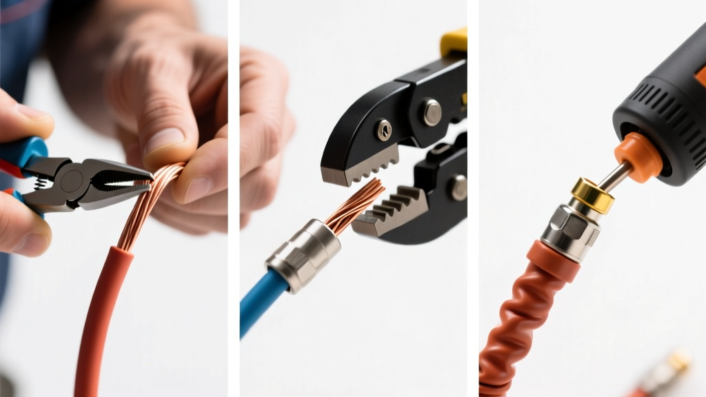
Place the Aptiv 10-12 AWG terminal into the ratcheting crimper. Insert the stripped 10 AWG wire into the terminal. The wire strands should be visible just past the front of the core crimp tabs, creating what is known as the 'front bellmouth'. This ensures 100% of the copper cross-section is captured inside the crimp barrel.
Squeeze the ratcheting crimper until the mechanism releases. The resulting crimp should feature a tight, uniform core crimp that cold-welds the copper strands, and a secondary insulation crimp that firmly grips the yellow cable seal and the GXL jacket. The insulation crimp provides the strain relief necessary to meet the USCAR-2 150N pull-out requirement.
Step 4: Visual Inspection and Tug Testing
Before inserting the terminal into the nylon housing, perform a visual inspection. Verify the bellmouth is present on both the front and rear of the core crimp. Ensure no rogue copper strands are escaping the crimp barrel, which could cause a short circuit inside the connector cavity. Perform a manual tug test by pulling the wire and the terminal in opposite directions with moderate force. The wire insulation should stretch before the crimp fails.
Step 5: Housing Insertion and Locking
Slide the yellow cable seal forward until it seats against the insulation crimp barrel. Align the terminal with the corresponding cavity in the Weather-Pack housing. Push the terminal straight in until you hear and feel a distinct 'click'. This indicates that the stainless steel locking barb on the terminal has snapped over the internal nylon retention shoulder. To verify, pull back gently on the wire. The terminal should not back out. If it does, the barb may be bent; use a small pick to gently lift the barb away from the terminal body and re-insert.
Application Example: Auxiliary Fuel Pump Harness Pinout
When wiring a high-pressure auxiliary fuel pump (commonly drawing 15-22 amps under load, necessitating 10 AWG wire to prevent voltage drop over long chassis runs), proper pin assignment and color coding are vital for future diagnostics.
| Connector Cavity | Terminal Type | Wire Color | Circuit Function |
|---|---|---|---|
| Pin 1 (A) | Male (15304717) | Red (10 AWG) | 12V+ Feed from Heavy-Duty Relay Pin 87 |
| Pin 2 (B) | Female (15304715) | Black (10 AWG) | Chassis Ground (Local Star Point) |
Note: Always route the Red 12V+ wire through a 30A MAXI fuse located within 18 inches of the battery positive terminal to protect the 10 AWG wire harness from dead-short thermal events.
Real-World Troubleshooting and Failure Modes
Even with proper installation, 10 gauge wire connector plugs operate in extreme environments. Use this decision tree to diagnose common harness failures:
Symptom: Connector Housing is Discolored or Melted
- Cause 1: High Resistance Crimp. If the crimper die was worn or the wire strands were nicked, the core crimp acts as a resistor. At 30A, a 0.05-ohm resistance generates enough heat (I²R losses) to melt the Nylon 66 housing.
- Cause 2: Terminal Fretting Corrosion. If the male and female terminals lose tension due to vibration, micro-arcing occurs. Fix: Replace both male and female terminals and apply a dielectric stabilant (e.g., Stabilant 22) to the mating surfaces.
Symptom: Intermittent Accessory Operation (Voltage Drop)
- Cause 1: Backed-Out Terminal. The locking barb failed to engage, and engine vibration pushed the terminal backward, breaking the mating contact. Fix: Extract the terminal using a specialized Weather-Pack removal tool (which depresses the internal retention tangs), lift the barb, and re-seat until it clicks.
- Cause 2: Seal Intrusion. If the yellow seal was not fully pushed forward before insertion, it can become wedged between the male and female mating surfaces, blocking electrical continuity. Fix: Extract, reposition seal, and re-insert.
Symptom: Green Crust (Copper Oxide) Inside the Connector
- Cause: Capillary Action. If the wire was stripped too far, exposed copper inside the seal cavity wicked moisture from the environment directly into the crimp barrel. Fix: Cut the harness back to clean copper, re-strip to exactly 6.0mm, and ensure the seal sits flush against the insulation crimp.
Conclusion
Mastering the installation of a 10 gauge wire connector plug is a fundamental skill for any automotive electrical specialist. By adhering to SAE wire standards, utilizing the correct Aptiv Weather-Pack components, and employing ratcheting crimp tooling, you ensure that your high-amperage circuits remain robust, sealed, and reliable across thousands of miles of harsh operating conditions. Never compromise on the crimp geometry or the environmental seal; in high-current automotive systems, the integrity of the connection dictates the longevity of the entire circuit.