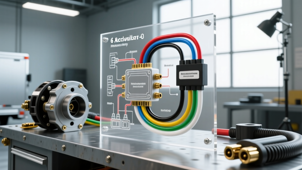
The Hidden Link: APP Sensors and Trailer Brake Modules
When modern heavy-duty trucks experience a sudden 'Service Trailer Brake System' warning alongside reduced engine power, most DIYers and fleet technicians immediately blame the 7-pin trailer connector or the Integrated Trailer Brake Control Module (ITBCM). However, the root cause frequently lies upstream in the drive-by-wire (DBW) throttle system. Specifically, a fault in the accelerator pedal assembly will trigger a cascading failure that disables trailer braking to prevent uncommanded trailer lock-up.
When consulting a 6 pin accelerator pedal position sensor wiring diagram, technicians must recognize that these circuits are not simple 12V switches. They are precision 5V analog signals governed by strict SAE redundancy standards. If the ECM detects an implausible signal or a voltage dropout in the pedal sensor harness, it instantly degrades the Tow/Haul mode and cuts power to the trailer brake controller. This guide provides a step-by-step troubleshooting flow to diagnose APP sensor wiring faults that masquerade as trailer brake failures.
Understanding the 6-Pin APP Sensor Topology
Heavy-duty applications (such as the GM 6.6L Duramax and 6.0L/6.6L gas V8s) utilize a 6-pin weather-sealed connector for the Accelerator Pedal Position (APP) sensor. Unlike older 3-pin throttle position sensors, the 6-pin design houses two completely isolated potentiometer or Hall-effect sensor circuits. This dual-redundancy is mandated for towing safety; if Signal 1 fails, the ECM can rely on Signal 2 to safely idle the engine and allow the driver to pull over.
The ITBCM continuously monitors the CAN-bus for APP plausibility. If the ECM flags a P2138 (Accelerator Pedal Position Sensor 1-2 Correlation) or P2120 (APP Sensor 1 Circuit Malfunction) code, the ITBCM assumes the driver's torque request is corrupted. To prevent the trailer brakes from applying at 100% force during a sensor short, the ITBCM disables the trailer brake output entirely.
6-Pin APP Sensor Pinout and Wiring Specifications
The following specification chart details the standard 6-pin GM HD APP sensor connector (often designated as Connector C1311 or similar depending on the model year). Always verify against your specific OEM service manual, but this topology represents the industry-standard dual-redundant layout.
| Pin | Circuit ID | Wire Color | AWG | Function | Voltage (Idle / WOT) |
|---|---|---|---|---|---|
| 1 | 595 | Dark Blue | 20 | APP Signal 1 | 0.8V / 3.8V |
| 2 | 1390 | Pink | 20 | 5V Reference 1 | 5.0V (Constant) |
| 3 | 1590 | Black/White | 20 | Low Reference (Ground) 1 | 0.0V |
| 4 | 1391 | Purple | 20 | 5V Reference 2 | 5.0V (Constant) |
| 5 | 1591 | Purple/White | 20 | Low Reference (Ground) 2 | 0.0V |
| 6 | 596 | Light Blue | 20 | APP Signal 2 | 0.4V / 1.9V |
Note: Signal 1 and Signal 2 operate on different voltage slopes. The ECM expects Signal 2 to read exactly half the voltage of Signal 1 at any given pedal position. A deviation of more than 10% triggers a plausibility fault and disables the trailer brakes.
Step-by-Step Troubleshooting Flow: Service Trailer Brake System
Follow this diagnostic decision tree when a customer complains of intermittent trailer brake loss, reduced power while towing, or a persistent 'Service Trailer Brake System' DIC message.
Step 1: Visual Harness Inspection (The Firewall Chafe)
Before unbolting the pedal assembly or back-probing the ECM, inspect the physical routing of the APP harness. The most common real-world failure mode occurs where the harness passes through the firewall grommet or zip-ties to the lower dash support brace.
- Symptom: Trailer brakes work when cold, but fail after the engine bay heats up or when the driver heavily depresses the pedal.
- Inspection Point: Check the 6-pin connector pigtail for micro-abrasions against the parking brake pedal bracket. A pinhole in the 20 AWG Pink (5V Ref) wire will short to the metal bracket, dropping the reference voltage to 0V and instantly killing the ITBCM output.
- Action: If the loom is split or wires are exposed, cut back to clean copper. Do not use electrical tape; use adhesive-lined heat shrink.
Step 2: DMM Back-Probing and 5V Reference Verification
If the visual inspection yields no results, you must test the live circuits. You will need a high-impedance Digital Multimeter (DMM) (>10 Megaohms) and fine T-pins to back-probe the connector without spreading the Metri-Pack 280 terminals.
- Turn the ignition to the 'ON' position (engine off).
- Back-probe Pin 2 (Pink) and Pin 4 (Purple). Both should read a stable 4.95V to 5.05V against a known good chassis ground.
- Diagnostic Branch: If Pin 2 reads 0V but Pin 4 reads 5V, you have an open circuit or short-to-ground on Circuit 1390 between the ECM and the pedal. The ECM has likely disabled the 5V driver to protect itself. Trace the wire back to the ECM C1 connector.
Step 3: Signal Sweep and Plausibility Testing
If the 5V references and grounds are intact, the sensor's internal wipers may be worn, creating a 'dead spot' that only manifests under heavy towing acceleration.
- Connect your DMM to Pin 1 (Dark Blue) and ground.
- Have an assistant slowly press the accelerator pedal from idle to Wide Open Throttle (WOT).
- The voltage must sweep smoothly from ~0.8V to ~3.8V without any sudden drops to 0V or spikes to 5V.
- Repeat the test on Pin 6 (Light Blue). The sweep should be smooth from ~0.4V to ~1.9V.
- The Trailer Brake Tie-In: If you see a momentary dropout on the DMM exactly when the driver hits 3/4 throttle (a common towing acceleration point), the ECM registers a plausibility error. The CAN-bus tells the ITBCM to abort the trailer brake PWM signal to prevent a jackknife event.
Proper Repair Protocols for Sensor Harnesses
When repairing a damaged 6-pin APP sensor harness, standard butt-crimps are unacceptable. The 20 AWG TXL (Thin-wall Cross-linked) wires carry low-voltage, high-sensitivity analog signals. A poor crimp will introduce resistance, altering the voltage sweep and causing phantom trailer brake faults.
- Wire Selection: Always use 20 AWG TXL or GXL automotive-grade wire. Standard hardware store THHN wire is too stiff and will crack under pedal vibration.
- Splicing Method: Use rosin-core solder and dual-wall adhesive heat shrink. The adhesive seals out moisture and prevents the 'green rot' (copper oxidation) that increases circuit resistance over time.
- Connector Terminals: If the 6-pin female terminals are spread or corroded, replace them with OEM Delphi Metri-Pack 280 series terminals. Use the proper ratcheting crimp tool to ensure the wire crimp and insulation crimp are secured to factory pull-out force specifications.
Aftermarket Brake Controller Integration Notes
For older heavy-duty trucks lacking a factory ITBCM, owners often install aftermarket proportional controllers like the Tekonsha Prodigy P3 or Curt Spectrum. While these controllers primarily rely on the Brake Pedal Position (BPP) switch and an internal inertia sensor, some advanced OEM-integrated tow packages tap the CAN-bus which includes APP data. Never attempt to splice an aftermarket trailer brake controller directly into the 5V APP signal wires to 'modulate' braking based on throttle position. This will pull down the ECM's 5V reference bus, potentially stalling the engine and destroying the throttle body actuators. Always use a dedicated CAN-bus decoder module or the factory brake switch feed as outlined in the GM Upfitter Body Builder Manuals.
Authoritative References
For deeper electrical diagnostics and CAN-bus topology mapping regarding trailer brake integration, consult the following industry standards:
- SAE International (J1939 / J2530) - Standards for Drive-by-Wire redundancy and heavy-duty vehicle network topologies.
- GM Upfitter / Body Builder Documentation - OEM wiring schematics, ITBCM integration guides, and tow-rating electrical requirements.
- etrailer.com Wiring FAQs - Practical field guides on 7-pin harness routing, brake controller signal loss, and ground fault isolation.
By understanding the critical relationship between the 6-pin accelerator pedal position sensor and the trailer brake module, you can accurately diagnose complex tow-mode faults, clear the 'Service Trailer Brake System' message, and ensure safe, proportional braking for heavy loads.