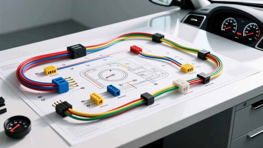
Understanding Tachometer Signal Types: The Core of Selection
When integrating aftermarket instrumentation into a vehicle, selecting the correct wiring diagram for auto gauge tachometer configurations requires a fundamental understanding of ignition signal architecture. A tachometer does not measure voltage amplitude; it measures the frequency of the ignition pulse, translating the duty cycle of a square wave into a readable RPM value. Whether you are wiring a classic muscle car with a points-style distributor, an 80s truck with an HEI module, or a modern LS-swapped chassis running Coil-On-Plug (COP), the signal source dictates the gauge selection and wiring methodology.
According to SAE International's J1113 standards on electromagnetic compatibility, automotive electrical environments are highly susceptible to Electromagnetic Interference (EMI). High-energy ignition systems like CDI (Capacitive Discharge Ignition) boxes and modern COP setups generate massive amounts of RF noise. Therefore, selecting a tachometer with built-in filtering or utilizing shielded wiring harnesses is not optional—it is a strict requirement for stable needle operation at high RPMs.
Product Comparison: Selecting the Right Auto Gauge Tachometer
Before cutting into your vehicle's harness, you must choose a gauge movement type that aligns with your ignition system's output. Below is a technical comparison of the three primary tachometer architectures available on the market.
| Movement Type | Signal Requirement | Response Time | Best Application | EMI Susceptibility |
|---|---|---|---|---|
| Air-Core (Analog) | 12V Square Wave | Instant (<5ms) | Racing, Carbureted V8s, HEI | High (Requires shielded wire) |
| Stepper Motor (Digital) | 5V-12V Logic or CAN | Fast (~20ms) | Street/Strip, LS Swaps, EFI | Low (Internal micro-filtering) |
| Inductive Clamp | Magnetic Flux (AC) | Slow (~100ms) | Diesel engines, Older Points | Very Low (Isolated sensor) |
1. Classic Air-Core Tachometers
Air-core gauges use a magnet suspended between four electromagnetic coils. They offer the fastest needle response, making them ideal for manual transmission drag racing where precise shift points are critical. However, because they rely on raw analog voltage manipulation, they are highly sensitive to voltage drops and EMI. Wiring an air-core tachometer requires strict adherence to 16 AWG power/ground circuits to prevent voltage starvation during high-load alternator output.
2. Digital Stepper-Motor Tachometers
Stepper-motor gauges (like those found in modern digital-analog hybrids) utilize a microcontroller to read the square wave frequency and physically drive a precision motor. These are the best choice for modern EFI swaps (such as GM LS or Ford Coyote engines) because their internal logic boards can easily scale 5V PCM signals without requiring external pull-up resistors or tach adapters.
Master Wiring Diagram for Auto Gauge Tachometer (Universal 4-Pin)
The industry standard for aftermarket analog and stepper-motor tachometers is the 4-pin blade connector. While specific wire colors may vary slightly by manufacturer (e.g., Auto Meter vs. Dakota Digital), the pinout architecture remains universally consistent. The following wiring diagram breakdown adheres to standard Auto Meter technical installation guidelines.
Pinout & Wire Gauge Specifications
- Pin 1: +12V Ignition Switched (Red Wire)
Requires 16 AWG stranded copper. Connect to an ignition-switched fuse block terminal. Do not connect to a constant 12V source, as this will drain the battery and potentially burn out the internal gauge logic board over time. - Pin 2: Ground (Black Wire)
Requires 16 AWG stranded copper. This is the most critical connection. Ground the black wire directly to the engine block, cylinder head, or a dedicated chassis ground stud using a solder-seal heat shrink terminal. Never ground a tachometer to the steering column or sheet metal dash, as ground loops will cause severe needle bounce. - Pin 3: Tach Signal (Green Wire)
Requires 18 AWG shielded wire. The shield must be grounded at the PCM/distributor end only to prevent ground loops. Connect to the negative terminal of the ignition coil, the dedicated tach output on an HEI module, or the PCM tach output pin. - Pin 4: Dimmer / Lighting (White Wire)
Requires 18 AWG standard wire. Connect to the vehicle's headlight switch dimmer circuit to allow the gauge backlighting to sync with the dash illumination.
Modern Engine Swap Integration: LS, Coyote, and K-Series
When using a universal wiring diagram for auto gauge tachometer setups on modern Coil-On-Plug (COP) engines, you cannot simply tap into an ignition coil. COP systems dwell the coil internally via the PCM and do not provide a traditional 12V square wave at the coil connector.
LS V8 PCM Pinout (Gen III/IV)
For GM LS swaps utilizing the factory ECU (e.g., PCM part number 12593305), the tachometer signal is output via Pin 10 on the Blue Connector. This pin outputs a 5V square wave calibrated to the engine's cylinder count. Most high-quality stepper-motor tachometers can read a 5V logic signal natively. If you are using an older air-core gauge, you must install a 12V pull-up resistor or a dedicated tach adapter (such as the MSD 8920) to step the 5V signal up to a 12V square wave.
Aftermarket CDI Boxes (MSD 6AL, Holley Sniper)
If your vehicle utilizes a Capacitive Discharge Ignition system, the tach signal wire must be connected to the dedicated grey tach output wire on the CDI box. According to Holley/MSD Ignition technical documentation, CDI boxes often require a 10k-ohm pull-up resistor wired between the 12V ignition source and the tach signal wire to stabilize the duty cycle and prevent the gauge needle from pegging to the maximum RPM limit upon key-on.
Cylinder Calibration & Dip Switch Configurations
A universal tachometer must be calibrated to the specific firing frequency of your engine. A V8 engine produces four ignition pulses per crankshaft revolution, whereas a 4-cylinder produces two. Most analog tachometers feature a 4-position DIP switch on the rear casing.
| Engine Configuration | Pulses per Revolution | Standard DIP Switch Setting |
|---|---|---|
| 4-Cylinder / 2-Rotor Rotary | 2 | ON - OFF - OFF - OFF |
| 6-Cylinder / 3-Rotor Rotary | 3 | OFF - ON - OFF - OFF |
| 8-Cylinder (Standard V8) | 4 | OFF - OFF - ON - OFF |
| 4-Cylinder Wasted Spark / 2-Cyl | 1 or 4 | Consult MFG (Usually ON-ON-OFF-OFF) |
Troubleshooting Signal Dropout and Needle Bounce
Even with the correct wiring diagram for auto gauge tachometer installations, real-world variables can introduce signal anomalies. Use this diagnostic decision tree to resolve common installation failures.
Symptom: Needle Bounces Erratically at High RPM
- Cause: EMI interference from spark plug wires or alternator whine inducing voltage in the signal wire.
- Fix: Reroute the green signal wire away from exhaust headers and spark plug wire looms. Ensure you are using 18 AWG shielded cable with the drain wire grounded at the ECU end. If using an HEI distributor, ensure the distributor cap RF suppressor is intact.
Symptom: Tachometer Reads Exactly Half the Actual RPM
- Cause: Cylinder calibration mismatch. The gauge is expecting an 8-cylinder pulse train but receiving a 4-cylinder pulse train (or vice versa).
- Fix: Flip the DIP switch on the rear of the gauge housing to match the engine's physical cylinder count. If using a tach adapter, adjust the internal trimpot or jumper pins on the adapter board.
Symptom: Needle Pegs to 8,000+ RPM Immediately Upon Key-On
- Cause: Short to ground on the signal wire, or a missing pull-up resistor on an aftermarket CDI box.
- Fix: Use a digital multimeter (DMM) set to continuity to test the green signal wire between the gauge and the ignition source. If the wire is intact, install a 10k-ohm, 1/2-watt resistor between the 12V ignition switched source and the tach signal wire to pull the logic high.
Symptom: Gauge is Completely Dead (No Backlight, No Movement)
- Cause: High-resistance ground connection or blown inline fuse.
- Fix: Check for 12V at the red wire with a DMM. If 12V is present, perform a voltage drop test on the black ground wire. A reading of more than 0.1V under load indicates a poor chassis ground. Sand the paint away to bare metal and apply dielectric grease to the grounding ring terminal.