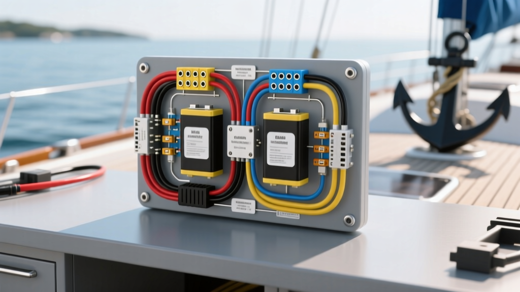
The Critical Role of a Proper Dual Battery Wiring Diagram for Boat Applications
When configuring a marine electrical system, relying on an automotive-style schematic is a dangerous error. A reliable dual battery wiring diagram for boat applications must account for harsh saltwater environments, constant vibration, and strict ignition-protection standards outlined by the American Boat and Yacht Council (ABYC). Unlike a truck or SUV, a boat's electrical failure doesn't just leave you stranded on the shoulder; it can result in a fire at sea, the loss of critical bilge pumps, or the failure of navigation electronics. This guide dissects the most common, catastrophic mistakes made when wiring dual marine battery banks and provides the exact specifications required to correct them.
Anatomy of a Safe Marine Dual Battery Setup
A standard dual-battery marine configuration separates the 'Starting' bank (dedicated to engine cranking) from the 'House' bank (dedicated to stereos, lights, live wells, and electronics). The two banks are managed by an Automatic Charging Relay (ACR), a Voltage Sensitive Relay (VSR), or a manual 1-2-BOTH-OFF switch. Below is the baseline specification chart for a typical 12V marine dual-battery system utilizing an ACR.
| Circuit Application | Recommended Wire (AWG) | Wire Type / Spec | Overcurrent Protection | Terminal Torque Spec |
|---|---|---|---|---|
| Main Battery to Starter | 1/0 AWG | UL 1426 Tinned Copper | Class T Fuse (300A) | 120 in-lbs (5/16' stud) |
| House Bank to DC Bus | 2 AWG | UL 1426 Tinned Copper | MRBF or Class T (150A) | 120 in-lbs (5/16' stud) |
| ACR / VSR Main Lugs | 4 AWG | UL 1426 Tinned Copper | 30A MAXI Fuse | 90 in-lbs (1/4' stud) |
| ACR Ignition Isolation Lead | 16 AWG | Marine Primary Wire | 5A Inline ATC Fuse | N/A (Spade Connector) |
| DC Negative Ground Bus | 2 AWG or 1/0 AWG | UL 1426 Tinned Copper | N/A (Negative) | 120 in-lbs (3/8' stud) |
Top 4 Fatal Mistakes in Boat Dual Battery Wiring
Mistake 1: Using Automotive Wire Instead of Marine-Grade Tinned Copper
The most pervasive error found in DIY boat wiring is the use of standard automotive copper wire (SAE J1128). Automotive wire features fewer copper strands and lacks a tinned coating. In a marine environment, exposed bare copper rapidly oxidizes, forming black copper oxide. This oxide is highly resistive, leading to severe voltage drops, overheated wires, and melted insulation. Furthermore, automotive wire lacks the fine stranding (Type 3) required to withstand the high-frequency vibrations of a marine engine bay. You must exclusively use SAE J1128 or UL 1426 marine-grade, tinned, fine-strand copper wire. ABYC color codes also dictate that DC negative/ground wires should be yellow (not black) to prevent fatal confusion with AC shore power black wires.
Mistake 2: Undersizing the ACR Control Wire and Ignoring Ignition Isolation
When installing an Automatic Charging Relay (ACR) like the industry-standard Blue Sea Systems 7610, installers often connect the two large battery studs and the small ground spade, but completely ignore the yellow/black ignition isolation wire. If this 16 AWG wire is not connected to an ignition-switched 12V source (via a 5A inline fuse), the ACR will remain active based solely on voltage sensing. If you are anchored with the engine off and the house bank voltage temporarily spikes due to solar charging or a stereo capacitor, the ACR will incorrectly combine the banks, potentially draining your starting battery and leaving you unable to crank the engine. Always route the ignition isolation lead to a verified 12V source that is only live when the key is in the 'ON' position.
Mistake 3: The 'Daisy-Chain' Grounding Topology Error
In a dual battery diagram for boat applications, the DC negative topology is just as critical as the positive supply. A massive mistake is 'daisy-chaining' ground wires from one device to the next, or tying multiple heavy ground lugs onto a single battery post using stacked rings. Stacked rings increase contact resistance and create a single point of failure. The correct methodology requires routing all DC negative wires to a dedicated, heavy-duty negative bus bar (such as a Blue Sea 250A or 600A bus bar with 3/8' or 5/16' studs). From the bus bar, a single, massive 1/0 AWG or 2 AWG tinned copper cable runs directly to the battery negative terminal. This star-ground topology ensures that high-draw devices like windlasses or stereo amplifiers do not induce voltage fluctuations that will reboot sensitive NMEA 2000 navigation networks.
Mistake 4: Violating ABYC E-11 Overcurrent Protection Placement
According to ABYC E-11 standards, overcurrent protection (fuses or circuit breakers) must be installed within 7 inches of the battery positive terminal. If the 7-inch rule cannot be physically met due to battery box constraints, the wire must be enclosed in a flexible, non-conducting conduit for its entire run to the fuse. Many DIYers place a fuse block 4 feet away from the battery. If a short occurs in those first 4 feet of unfused wire, the battery will dump thousands of amps of dead-short current, instantly welding metal, melting the battery case, and igniting a catastrophic fire in the bilge. Utilize Marine Rated Battery Fuses (MRBF) which mount directly onto the battery terminal ring, ensuring zero unprotected wire length.
Step-by-Step Troubleshooting Decision Tree
When your dual battery system fails to perform as expected, use this diagnostic tree to isolate the fault safely.
- Symptom: Starting battery is dead after a night of anchoring, despite the ACR being installed.
- Cause A: ACR ignition isolation wire (yellow/black) is disconnected or blown 5A inline fuse.
- Fix A: Test yellow/black wire for 12V only when key is ON. Replace fuse or re-route to ignition switch.
- Cause B: House bank voltage is dropping below 12.3V, causing the ACR's under-voltage lockout to fail, keeping the relay closed.
- Fix B: Load test house bank batteries. Replace degraded cells that cannot hold surface charge.
- Symptom: ACR is clicking rapidly (cycling on and off) while the engine is idling.
- Cause: Voltage drop across undersized ACR wiring or corroded battery terminals is causing the ACR to sense a false low-voltage state on one bank, triggering a disconnect, which then raises the voltage, triggering a reconnect.
- Fix: Clean all battery terminals with a wire brush. Verify ACR main cables are at least 4 AWG and torqued to 90 in-lbs. Check for black copper oxide under the crimp lugs.
Authoritative References & Safety Standards
Designing and troubleshooting marine electrical systems requires adherence to established maritime safety codes. For complete wiring diagrams, torque specifications, and voltage drop calculators, always consult the following resources:
- American Boat and Yacht Council (ABYC) - E-11 AC & DC Electrical Systems on Boats.
- Blue Sea Systems Circuit Documents - ACR/VSR installation schematics and technical bulletins.
- SAE International - J1128 Low Tension Primary Cable specifications for marine and automotive use.
By strictly following a verified dual battery wiring diagram for boat applications and avoiding these common pitfalls, you ensure your vessel remains safe, compliant, and ready for the water.