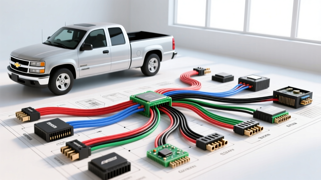
The Chevrolet S10, particularly the second generation (1994–2004) equipped with the 4.3L Vortec V6, represents a transitional era in GM truck electrical architecture. Moving away from simple analog circuits, these trucks rely heavily on the Powertrain Control Module (PCM) and Class 2 serial data networks. Interpreting a factory Chevrolet S10 wiring diagram requires more than just tracing lines; it demands an understanding of GM's specific wire color coding, gauge requirements, and multi-pin connector layouts. This complete walkthrough dissects the core electrical schematics, focusing on the PCM pinouts, fuel delivery circuits, and critical sensor networks to help you diagnose and repair complex electrical gremlins.
Decoding the S10 PCM Connector Layout
The 1996–2002 Chevrolet S10 4.3L Vortec PCM utilizes three distinct 32-way connectors, typically color-coded for easy identification on the bench and in the engine bay. When reading your Chevrolet S10 wiring diagram, you will see these referenced as C1, C2, and C3. The C1 connector (Blue) primarily handles injector drivers and main power/ground circuits. The C2 connector (Clear) is dedicated to sensor inputs, including the Mass Air Flow (MAF) and Throttle Position Sensor (TPS). The C3 connector (Black) manages ignition coil drivers, serial data, and secondary emissions controls.
Understanding the pinout is critical because GM uses specific wire gauges for high-current circuits versus low-voltage signal circuits. For instance, the PCM main power feeds utilize 12 AWG wire to prevent voltage drop, while sensor signal wires are typically 18 AWG or 20 AWG to maintain signal integrity and reduce capacitance.
Critical PCM Pinout Reference (1998-2002 4.3L V6)
| Connector | Pin | Wire Color | Circuit Function | Wire Gauge |
|---|---|---|---|---|
| C1 (Blue) | 1 | Dark Blue | Injector 1 Control | 18 AWG |
| C1 (Blue) | 9 | Black/White | PCM Main Ground | 12 AWG |
| C1 (Blue) | 20 | Pink | Ignition 12V Feed | 14 AWG |
| C2 (Clear) | 21 | Yellow | MAF Signal Input | 18 AWG |
| C2 (Clear) | 22 | Black/White | MAF Low Reference | 18 AWG |
| C3 (Black) | 32 | Dark Green | Class 2 Serial Data | 18 AWG |
Critical Grounding Points and Wire Gauges
In GM truck electrical systems, poor grounding accounts for over 60% of misdiagnosed sensor failures. The Chevrolet S10 wiring diagram routes several critical PCM and sensor grounds to specific chassis and engine block nodes. If you are experiencing erratic shifting, random misfires, or a no-start condition, verifying these ground nodes with a voltage drop test is mandatory before replacing the PCM.
S10 Primary Ground Node Specifications
| Ground ID | Location | Primary Wire Color | Gauge | Common Failure Symptom |
|---|---|---|---|---|
| G100 | Battery to Left Frame Rail | Black | 4 AWG | Slow cranking, total electrical death |
| G110 | Rear of Engine Block (Bellhousing) | Black/White | 12 AWG | Erratic TPS, PCM communication loss |
| G112 | Right Cylinder Head | Black | 12 AWG | Injector misfires, O2 sensor skew |
| G113 | Left Cylinder Head | Black | 12 AWG | CKP signal loss, no-start |
Diagnostic Tip: Do not rely on a simple continuity test for grounds. A single strand of 12 AWG wire will show continuity but will fail under load. Use a digital multimeter to perform a voltage drop test across the ground circuit while the engine is cranking or running. A healthy PCM ground should read less than 0.10V under load.
Fuel Pump Relay and Feed Circuit Walkthrough
The fuel pump circuit is a frequent failure point on high-mileage S10s. Unlike older vehicles where the ignition switch directly powered the pump, the S10 utilizes a PCM-controlled relay with a prime sequence. When you turn the key to the 'ON' position, the PCM energizes the fuel pump relay for approximately two seconds to prime the fuel rails. If it does not see a Crankshaft Position Sensor (CKP) signal, it shuts the relay off.
Tracing the Fuel Pump Circuit
- Relay Power Feed (Pin 30): An Orange 10 AWG wire supplies constant battery voltage from the underhood fuse block to the relay.
- Relay Coil Ignition (Pin 86): A Pink/Black 18 AWG wire provides 12V from the ignition switch when in the 'Run' or 'Start' position.
- PCM Trigger (Pin 85): The PCM provides the ground path for the relay coil via a Dark Green/White 18 AWG wire. When the PCM grounds this circuit, the relay clicks closed.
- Pump Feed (Pin 87): A Gray 12 AWG wire carries the high-current 12V feed from the relay directly to the fuel pump sender assembly in the tank.
- Pump Ground: A Black 12 AWG wire grounds the pump to the chassis near the fuel tank (G400).
Real-World Failure Mode: The Gray 12 AWG feed wire is notorious for chafing against the frame rail near the fuel tank crossmember, leading to a dead short that blows the 20A F/PMP fuse. Always inspect this physical routing before condemning the fuel pump module.
Engine Sensor Wiring: MAF and CKP Diagnostics
Accurate interpretation of the Chevrolet S10 wiring diagram is vital when diagnosing driveability issues related to the Mass Air Flow (MAF) and Crankshaft Position (CKP) sensors. Both sensors rely on a clean 5V or 12V reference and a dedicated low-reference ground back to the PCM.
Mass Air Flow (MAF) Sensor Pinout
The GM hotwire MAF sensor uses a 3-pin connector. Pin A is the Ground/Low Reference (Black/White, 18 AWG). Pin B is the Signal Output (Yellow, 18 AWG), which outputs a variable frequency signal (Hz) rather than a simple DC voltage. Pin C is the 12V Ignition Feed (Pink, 18 AWG). If the MAF reads 0 Hz at idle, check the Pink wire for 12V and the Black/White wire for less than 0.05 ohms of resistance to the G110 engine ground.
Crankshaft Position (CKP) Sensor Pinout
The 4.3L Vortec uses a 3-wire Hall-effect CKP sensor mounted near the harmonic balancer. Pin A is the Low Reference (Purple/White). Pin B is the Signal circuit (Yellow) returning a 3x or 24x pulse train to the PCM. Pin C is the 12V Reference feed (Light Blue). A common wiring failure here involves the harness rubbing against the A/C compressor bracket, causing the Light Blue 12V reference wire to short to ground, instantly killing the CKP signal and causing a crank-no-start condition.
OBD-II Data Link Connector (DLC) Pinout
To communicate with the S10's PCM, scan tools interface with the 16-pin Data Link Connector located under the driver's side dash. Understanding the DLC pinout is essential for diagnosing communication errors (e.g., U1000 Class 2 Serial Data codes).
- Pin 2: Class 2 Serial Data (Dark Green, 18 AWG) - The primary communication bus.
- Pin 4: Chassis Ground (Black, 14 AWG).
- Pin 5: Signal Ground (Black/White, 18 AWG) - Dedicated PCM logic ground.
- Pin 16: Battery Positive (Orange, 12 AWG) - Constant 12V to power the scan tool.
If your scan tool powers on but fails to link with the PCM, verify Pin 5 (Signal Ground). If the PCM loses its dedicated signal ground, it will shut down the Class 2 serial data driver to protect its internal circuitry, resulting in a complete loss of scanner communication.
Authoritative References and Further Reading
For exact year-over-year variations, always consult the official factory service manuals. The wiring schematics and pinouts detailed in this walkthrough are based on the core architecture of the 1996-2002 GM 4.3L Vortec platform. For deeper study and official GM wiring diagrams, refer to Helm Incorporated, the official publisher of GM service manuals. For standardized diagnostic protocols regarding the Class 2 serial data network, consult the SAE J1850 Standard documentation. Additionally, comprehensive aftermarket schematic references can be cross-referenced via the AutoZone Repair Guide Library for visual diagram layouts.