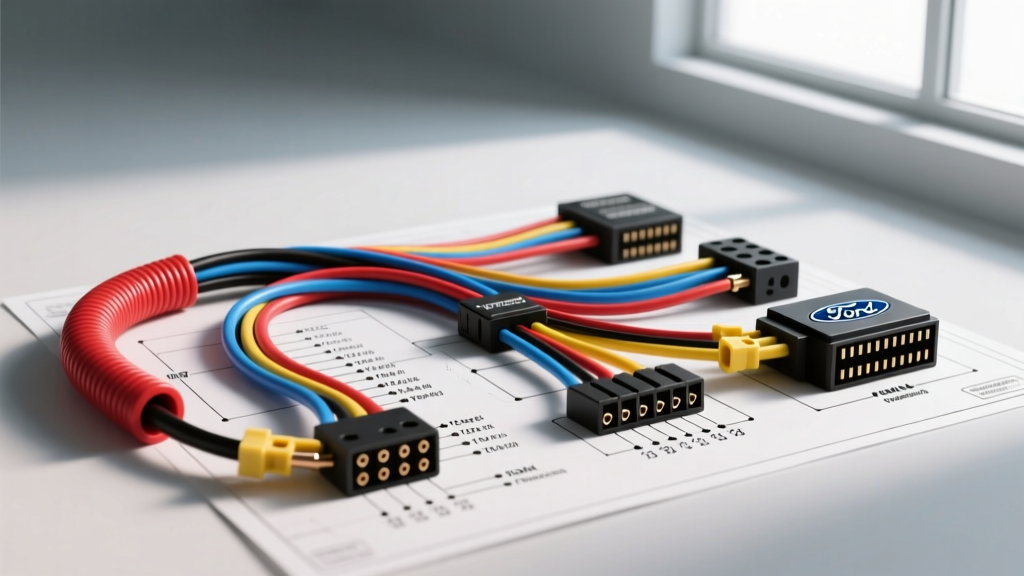
Introduction to the 7.3L HEUI Electrical Architecture
The Ford 7.3L Powerstroke diesel engine utilizes a Hydraulic Electronic Unit Injector (HEUI) system that fundamentally differs from modern common-rail or mechanical injection setups. Instead of relying on a high-pressure fuel pump to atomize diesel, the HEUI system uses high-pressure engine oil to drive a piston inside the injector, which in turn pressurizes and injects the fuel. To actuate the poppet valves that control this oil flow, the system requires a massive, instantaneous electrical spike. This is where the Injector Driver Module (IDM) comes into play. When sourcing a precise wiring diagram for the Ford 7.3L Powerstroke IDM and injector harness, technicians must understand that the IDM steps up the vehicle’s standard 12V DC system to approximately 110V to 140V DC to fire the injector solenoids.
This advanced technical deep dive provides a comprehensive schematic breakdown of the IDM-to-PCM communication circuits, the under-valve cover harness (UVCH) routing, and the high-current power feeds required to keep the HEUI system operational. Whether you are diagnosing a cylinder contribution balance code (P0263-P0284), an IDM failure (P1316), or a complete crank-no-start condition, understanding the exact pinouts, wire gauges, and OEM color codes is mandatory for an accurate repair.
Architecture of the IDM Power and Ground Circuits
Before analyzing the logic signals, we must address the high-current power delivery required by the IDM. The module is essentially a high-frequency switching power supply and an H-bridge motor driver combined into one sealed aluminum unit. Because it must charge capacitors to generate 140V spikes for up to four injectors simultaneously (in a split-fire or sequential sequence depending on the calibration), the 12V input circuit requires heavy-gauge wiring.
IDM Power Feed Specifications
| Circuit Function | Wire Color (OEM) | AWG Size | Connector / Pin | Voltage / Spec |
|---|---|---|---|---|
| Battery Feed (Ignition Run/Start) | Yellow/Light Green (Y/LG) | 10 AWG | IDM 120-Pin, Pin 11 | 12V - 14.5V DC |
| IDM Relay Output (Switched 12V) | White/Red (W/R) | 10 AWG | IDM 120-Pin, Pin 72 | 12V - 14.5V DC |
| Main Power Ground | Black/Yellow (BK/Y) | 10 AWG | IDM 120-Pin, Pin 24 | < 0.05V Drop |
| Logic Ground (PCM Reference) | Black/White (BK/W) | 18 AWG | IDM 120-Pin, Pin 48 | < 0.02V Drop |
Diagnostic Note: Voltage drop testing on the 10 AWG power and ground circuits is critical. According to SAE International heavy-duty electrical standards, any voltage drop exceeding 0.1V on the main 12V feed under cranking load will cause the IDM’s internal step-up transformer to starve, resulting in weak injector solenoid actuation and a rough cold start.
PCM to IDM Communication: FDCS and CI Circuits
The Powertrain Control Module (PCM) does not send high voltage to the injectors. Instead, it sends a low-voltage, high-speed digital square wave to the IDM. This signal is known as the Fuel Delivery Command Signal (FDCS). The IDM reads the pulse width and timing of the FDCS, then switches the 140V output to the corresponding injector solenoid. Simultaneously, the IDM sends a feedback signal back to the PCM known as the Cylinder Identification (CI) or IDM Feedback signal, confirming that the high-voltage circuit successfully fired.
PCM to IDM Logic Pinout
| Signal Name | Function | Wire Color | PCM Pin | IDM Pin |
|---|---|---|---|---|
| FDCS (Fuel Delivery Command) | Injector timing & pulse width | Dark Blue/Orange (DB/O) | PCM Pin 73 | IDM Pin 18 |
| CI (Cylinder Identification) | IDM feedback / error reporting | White/Purple (W/P) | PCM Pin 94 | IDM Pin 49 |
| IDM Enable (V_REF) | Module wake-up / enable signal | Red/Yellow (R/Y) | PCM Pin 87 | IDM Pin 71 |
When using a digital storage oscilloscope (DSO) to view the FDCS signal, technicians should expect to see a clean 0V to 5V square wave. The frequency and duty cycle will vary dynamically with engine RPM and throttle position. If the FDCS signal is present at the IDM connector but the engine misfires, the fault lies within the IDM’s internal H-bridge or the high-voltage injector harness. For deeper validation of PCM logic states, refer to the Motorcraft OEM Diagnostic Manuals for specific 7.3L flash calibration variations.
Under-Valve Cover Harness (UVCH) and Injector Pinout
The most common failure point in the 7.3L injector wiring diagram is the Under-Valve Cover Harness (UVCH). This harness routes the high-voltage signals from the external engine harness, through the valve cover gasket, and directly to the HEUI injectors. The connection is made via a 9-pin rectangular connector integrated directly into the valve cover gasket itself.
Left Bank (Driver Side) UVCH 9-Pin Connector Layout
The left bank controls cylinders 2, 4, 6, and 8. The injector solenoids on a 7.3L are not individually grounded; they share a common high-voltage feed per bank, while the IDM switches the ground path for each specific cylinder.
| Pin | Function | Wire Color (External Harness) | AWG |
|---|---|---|---|
| 1 | Glow Plug #2 | Light Blue/Black (LB/BK) | 12 AWG |
| 2 | Glow Plug #4 | Light Blue/Red (LB/R) | 12 AWG |
| 3 | Glow Plug #6 | Light Blue/White (LB/W) | 12 AWG |
| 4 | Glow Plug #8 | Light Blue/Yellow (LB/Y) | 12 AWG |
| 5 | Injector Common (Left Bank) | Dark Blue/Orange (DB/O) | 14 AWG |
| 6 | Injector #2 Control | White/Red (W/R) | 14 AWG |
| 7 | Injector #4 Control | White/Brown (W/BR) | 14 AWG |
| 8 | Injector #6 Control | White/Orange (W/O) | 14 AWG |
| 9 | Injector #8 Control | White/Yellow (W/Y) | 14 AWG |
Right Bank Note: The right bank (passenger side, cylinders 1, 3, 5, 7) follows an identical 9-pin layout, but the injector control wire colors differ (e.g., Cylinder 1 is typically Dark Blue/White, Cylinder 3 is Dark Blue/Yellow, etc.). The common wire for the right bank is typically White/Black (W/BK).
Advanced Diagnostics: UVCH Failure Modes and Torque Specifications
The integration of the 9-pin electrical connector into the rubber valve cover gasket is a known engineering vulnerability. The high-voltage spikes (140V) combined with the extreme thermal cycling of the diesel engine cause the metal contacts inside the gasket to fret and oxidize. This results in increased electrical resistance. Because the IDM monitors the inductive kickback of the solenoid, high resistance will cause the IDM to log a cylinder fault and deactivate the injector to protect the H-bridge circuit.
Preventing UVCH Connector Crushing
When replacing the valve cover gaskets and UVCH, technicians frequently over-torque the valve cover bolts, which physically crushes the 9-pin connector traces embedded in the rubber. The OEM specification for the 7.3L valve cover bolts is strictly 89 in-lbs (10 Nm). This is inch-pounds, not foot-pounds. Using a standard 1/2-inch drive torque wrench will instantly destroy the gasket connector. Always use a calibrated 1/4-inch drive inch-pound torque wrench and follow the star-pattern tightening sequence outlined in the Fleetpride Heavy Duty Service Guidelines.
Oscilloscope Testing of the Injector Solenoid
To definitively diagnose a failing injector solenoid versus a failing IDM channel, an oscilloscope must be connected to the injector control wire (e.g., Pin 6, White/Red for Cylinder 2) and the common wire (Pin 5, Dark Blue/Orange).
- Healthy Waveform: When the IDM fires, the scope will show a rapid spike to +140V, followed by a decay to a holding voltage of roughly +48V to +70V. When the IDM shuts off the circuit, the collapsing magnetic field of the solenoid will generate a massive negative inductive spike (often exceeding -200V) before settling back to 0V.
- Open Circuit (Broken UVCH): The scope will show the IDM attempting to fire, but the voltage will instantly rail to the maximum open-circuit limit of the IDM (often +180V or higher) with no current ramp, and the inductive spike upon shutdown will be entirely absent.
- Short to Ground: The waveform will appear as a flat line near 0V, and the IDM will instantly abort the pulse, often triggering a hard P1316 (IDM Codes) or P1293 (Injector High Side Open/Short) diagnostic trouble code.
By combining this advanced wiring diagram data with oscilloscope validation, technicians can accurately isolate 7.3L Powerstroke HEUI electrical faults without resorting to unnecessary, expensive parts swapping.