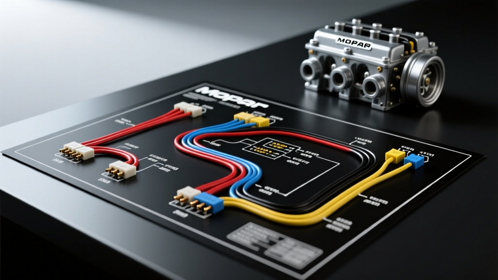
Introduction to the Mopar Electronic Ignition Swap
Upgrading a classic Chrysler, Dodge, or Plymouth V8 from a breaker-point distributor to a solid-state electronic ignition is one of the most reliable performance modifications you can perform. The classic Mopar Electronic Ignition System—often recognized by its iconic 'orange box' or 'chrome box' Ignition Control Module (ICM)—eliminates point bounce, dwell variation, and condenser failures. However, the success of this swap relies entirely on executing the Mopar electronic ignition wiring diagram with precision. A single misrouted wire or an incorrect coil pairing will result in a dead spark or a melted control module.
This practical how-to guide provides the exact wiring schematics, wire color codes, AWG specifications, and installation procedures required to wire a 4-pin Mopar Electronic Ignition Conversion Kit. Whether you are working on a 318, 340, 360, 383, or 440 cubic inch engine, the foundational electrical architecture remains consistent. We will cover the critical magnetic pickup air gaps, the often-misunderstood ballast resistor circuit, and real-world diagnostic procedures.
Core Components and Electrical Requirements
Before cutting or crimping a single wire, you must verify that your hardware matches the electrical requirements of the Mopar 4-pin ICM. The most common failure mode in aftermarket Mopar ignition swaps is pairing the module with an incompatible ignition coil. According to Stellantis TechAuthority service documentation, the standard Mopar 4-pin module requires a specific primary resistance range to operate safely with the factory-style ballast resistor.
- Ignition Control Module (ICM): 4-Pin Mopar Electronic Ignition Module (OEM style or high-performance aftermarket equivalent).
- Ignition Coil: Must have a primary resistance of 1.2 to 1.5 ohms. Do NOT use a low-resistance HEI-style coil (0.5 ohms) unless you are utilizing a specialized 12V constant-duty module.
- Ballast Resistor: Standard Mopar 1.2 to 1.5 ohm ceramic ballast resistor.
- Distributor: Mopar magnetic pickup distributor with vacuum advance.
- Connectors: Weather-Pack or OEM-style 4-pin sealed connectors with silicone seals to prevent moisture-induced misfires.
Mopar Electronic Ignition Wiring Specification Chart
The following table outlines the exact wire colors, functions, and American Wire Gauge (AWG) requirements for the main harness. Adhering to these gauge sizes ensures minimal voltage drop across the firewall and to the ignition coil.
| Wire Color | Function / Destination | Recommended AWG | Technical Notes |
|---|---|---|---|
| Red | Ignition Switch (Run/Start 12V) | 12 AWG | Connects to the IGN 1 terminal on the ignition switch or the 'run' side of the ballast resistor. |
| Green | Coil Positive (+) | 14 AWG | Routes from the ICM to the positive terminal of the ignition coil. |
| Blue | Coil Negative (-) / Tachometer | 14 AWG | Connects to the coil negative terminal. Splice a 16 AWG wire here for the tachometer signal. |
| Black | Chassis / Engine Ground | 10 or 12 AWG | Must ground directly to the engine block or intake manifold, NOT the firewall sheet metal. |
| Orange / Purple | Distributor Magnetic Pickup | 18 AWG | Polarity matters. Orange to Orange, Purple to Purple (or Yellow/Green on later models). Use shielded wire if routing near headers. |
The Mopar Electronic Ignition Wiring Diagram Breakdown
Understanding the flow of current is vital for troubleshooting. The Mopar system relies on a switched 12V source to wake up the ICM, while the ballast resistor regulates the voltage reaching the coil during the 'Run' cycle. Here is the logical flow of the Mopar electronic ignition wiring diagram:
- Power Feed: 12V from the ignition switch (Run position) enters the Red wire of the ICM harness. This same 12V feed also supplies the input side of the ceramic ballast resistor.
- Ballast to Coil: The output side of the ballast resistor drops the voltage to roughly 7V-9V and sends it to the Coil Positive (+) terminal. The Green wire from the ICM also connects to this Coil Positive (+) terminal to monitor dwell and saturation.
- Switching Ground: The Blue wire from the ICM connects to the Coil Negative (-) terminal. The ICM acts as a high-speed electronic switch, grounding and ungrounding the Blue wire to collapse the magnetic field in the coil, creating the spark.
- Magnetic Trigger: As the distributor reluctor wheel spins, the magnetic pickup generates a low-voltage AC signal (via the Orange and Purple wires) that tells the ICM exactly when to trigger the Blue wire ground.
Step-by-Step Installation Guide
Follow these steps to ensure a factory-correct, reliable installation. Reference standard SAE International automotive electrical practices for proper crimping and heat-shrink procedures.
Step 1: Distributor Preparation and Air Gap Verification
Before dropping the distributor into the engine, you must verify the magnetic pickup air gap. If the reluctor teeth are too close to the stator, it will physically strike and destroy the pickup. If too far, the signal will be too weak to trigger the ICM at low cranking speeds.
- Use a brass feeler gauge (steel gauges will attract the magnet and yield false readings).
- Align a reluctor tooth directly with the pickup stator.
- Adjust the pickup plate until the gap measures exactly 0.010 to 0.014 inches.
- Lock down the adjustment screw and apply a drop of blue threadlocker.
Step 2: Mounting the Ignition Control Module (ICM)
The ICM generates significant heat during operation. It must be mounted to a metal surface that acts as a heat sink. Do not mount it to plastic, fiberglass, or over sound deadening material. Apply a thin layer of silicone thermal heat sink compound to the back of the ICM before bolting it to the firewall or inner fender well using stainless steel hardware.
Step 3: Wiring the Ballast Resistor
Mount the ceramic ballast resistor on the firewall near the ICM. Connect the 12V IGN 'Run' wire to one terminal. Connect the other terminal to the Coil Positive (+) post. Crucial Note: If your vehicle uses a 5-pin module or a factory 'Start' retard circuit, a second wire from the ignition switch 'Start' position must bypass the ballast resistor and connect directly to the Coil Positive (+) post to provide full 12V during cranking. For a standard 4-pin aftermarket swap, the single ballast setup is sufficient.
Step 4: Routing and Securing the Harness
Route the distributor pickup wires (Orange and Purple) down the firewall and into the engine bay. Keep these wires at least 4 inches away from exhaust headers, spark plug wires, and the alternator to prevent Electromagnetic Interference (EMI). Wrap the harness in split-loom tubing and secure it with UV-resistant zip ties. Use dielectric grease on the distributor connector to prevent corrosion.
The Ballast Resistor Dilemma: Retain or Bypass?
A frequent question in the Mopar community is whether the ballast resistor can be eliminated. The answer depends entirely on your coil and module pairing. The standard Mopar 4-pin ICM is designed to operate with a 1.2 to 1.5 ohm coil and a 1.2 to 1.5 ohm ballast resistor. During the 'Run' cycle, the ballast drops the system voltage to protect the coil from overheating and to extend the life of the ICM's internal power transistor.
If you bypass the ballast resistor and feed 14.5V (alternator voltage) directly into a 1.5 ohm coil, the coil will overheat, and the excessive current draw will eventually burn out the ICM. Conversely, if you use a low-resistance 0.5 ohm 'HEI-style' coil with the Mopar ballast resistor, the voltage drop will be so severe that the coil will not saturate, resulting in a weak, yellow spark that will misfire under load. Always match the coil's primary resistance to the manufacturer's specifications for your specific ICM. For more on ignition coil saturation and dwell times, consult Holley Performance Tech resources.
Real-World Troubleshooting and Diagnostics
If your engine cranks but fails to start after following this Mopar electronic ignition wiring diagram, use this diagnostic decision tree to isolate the fault without throwing parts at the problem.
Symptom: No Spark at the Plugs
- Check the ICM Ground: Use a digital multimeter (DMM) to check resistance between the ICM mounting bracket and the negative battery terminal. It must read less than 0.2 ohms. Clean the firewall mounting point down to bare metal.
- Verify 12V at the Red Wire: With the key in the 'Run' position, probe the Red wire at the ICM connector. You should see full battery voltage (12V+). If 0V, check the ignition switch and firewall bulkhead connector.
- Test the Magnetic Pickup: Unplug the distributor connector. Set your DMM to Ohms (Ω). Probe the two pins on the distributor side (Orange and Purple). A healthy Mopar magnetic pickup will read between 800 and 2400 ohms at room temperature. If it reads 'OL' (open) or 0 (short), the internal pickup winding is destroyed.
Symptom: Engine Starts, but Misses at High RPM
- Check Coil Primary Resistance: Ensure you are not using a 0.5 ohm coil with the factory ballast. The voltage reaching the coil is too low to saturate the core quickly enough for high-RPM firing.
- Inspect the Tachometer Feed: If you spliced a tachometer wire into the Blue (Coil Negative) wire, ensure the splice is soldered and heat-shrunk. A loose crimp here will interrupt the ICM's ground path, causing random high-RPM misfires.
- Distributor Cap and Rotor: Electronic ignitions generate higher secondary voltage than points. Ensure you are using a premium cap and rotor with brass contacts, not cheap aluminum, which can arc internally under high voltage.
Final Inspection
Once the engine fires, use a timing light to verify your base timing. Because the Mopar electronic ignition eliminates the mechanical dwell variations inherent in breaker-point systems, your timing will remain incredibly stable across the RPM range. Re-torque your distributor hold-down clamp after the first heat cycle, and apply a final coat of dielectric grease to the bulkhead connectors to ensure decades of reliable, maintenance-free ignition performance.