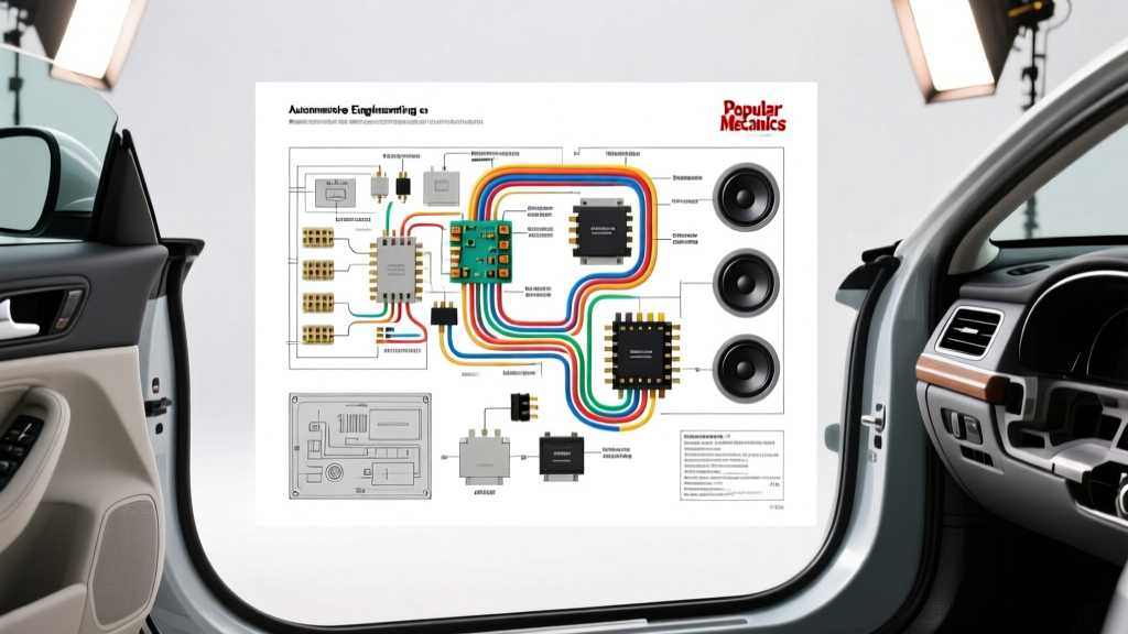
Introduction: Why the Diagram Dictates the Budget
Upgrading your vehicle's factory audio system is rarely a simple plug-and-play affair. To achieve high-fidelity sound and avoid catastrophic electrical failures, interpreting a precise wiring diagram for speakers is mandatory. However, many DIY installers focus solely on the cost of the head unit and drivers, severely underestimating the tooling, wire gauges, and integration modules required to execute the schematic correctly. This cost and tool requirements analysis breaks down exactly what you need to read, trace, and terminate automotive speaker wiring, ensuring your investment is protected against shorts, impedance mismatches, and moisture intrusion.
Essential Tools for Navigating Speaker Wiring Diagrams
Before cutting a single wire, you must assemble the proper diagnostic and termination tools. Relying on a test light instead of a digital multimeter can lead to blown head unit output ICs, especially in modern vehicles with Class-D factory amplifiers.
Diagnostic & Testing Equipment
- Digital Multimeter (DMM): A true-RMS DMM (such as the Fluke 115 or 87V) is non-negotiable. You will use this to verify continuity, measure DC offset voltage on factory amplified lines, and check for parasitic draws. Estimated Cost: $60 - $350.
- Inductive Tone Generator (Fox & Hound): When the factory wiring diagram for speakers lacks clear color coding or when tracing wires through a complex A-pillar grommet, an inductive probe allows you to identify specific speaker runs without piercing the wire insulation. Estimated Cost: $35 - $85.
- Phase Tester / Polarity Checker: Ensures all speaker cones are moving outward simultaneously to prevent acoustic cancellation. Estimated Cost: $40 - $60.
Termination & Routing Tools
- Ratcheting Wire Crimper: For 16 AWG to 12 AWG insulated and non-insulated terminals. A ratcheting mechanism ensures a gas-tight crimp that will not vibrate loose inside a door panel. Estimated Cost: $35 - $70.
- Precision Wire Strippers: Capable of stripping 22 AWG to 10 AWG without nicking the copper strands. Nicked strands reduce current capacity and create hot spots. Estimated Cost: $25 - $45.
- Variable Temperature Heat Gun: Adhesive-lined marine heat shrink requires exactly 120°C to 135°C to activate the inner thermoplastic sealant, preventing corrosion in high-moisture door environments. Estimated Cost: $40 - $90.
- Nylon Trim Removal Kit: Essential for prying off door panels and dash bezels without shorting exposed metal clips against live wiring or damaging the vehicle's interior. Estimated Cost: $15 - $25.
Material Costs: Wire Gauges, Connectors, and Adapters
The materials you choose must align with the power specifications outlined in your schematic. Using 18 AWG wire for a 300-watt subwoofer will result in severe voltage drop and potential wire melting. Below is a cost and application chart based on SAE J1128 low-voltage automotive wire standards and CTA power ratings.
| Wire Gauge (AWG) | Max Power Rating (RMS) | Typical Cost per Ft | Best Application |
|---|---|---|---|
| 18 AWG | Up to 50W | $0.15 - $0.20 | OEM replacement, low-power tweeters |
| 16 AWG | Up to 100W | $0.25 - $0.35 | Standard aftermarket coaxial & components |
| 14 AWG | Up to 200W | $0.45 - $0.60 | High-power mid-bass drivers, short runs |
| 12 AWG | Up to 400W | $0.80 - $1.20 | Subwoofers, amplifier output runs |
Connector & Adapter Costs: Purchasing OEM-to-aftermarket harness adapters (e.g., Metra or Scosche) saves hours of splicing. A standard 4-channel adapter harness costs between $8 and $18. If your vehicle uses proprietary connectors, such as the Ford 6-pin or Chrysler 10-pin, expect to pay up to $25 for the specific adapter.
Decoding the Wiring Diagram for Speakers: OEM vs. Aftermarket
Understanding the color codes and pinouts in your schematic is critical. The Consumer Technology Association (CTA, formerly EIA) established standard color codes for aftermarket car audio, but OEM diagrams often deviate significantly.
Standard CTA Aftermarket Color Codes
- Front Left: White (Positive), White with Black Stripe (Negative)
- Front Right: Gray (Positive), Gray with Black Stripe (Negative)
- Rear Left: Green (Positive), Green with Black Stripe (Negative)
- Rear Right: Purple (Positive), Purple with Black Stripe (Negative)
OEM Variations and Pinouts
When consulting a factory wiring diagram for speakers, you will frequently encounter striped wires that do not follow CTA rules. For example, in many Ford vehicles utilizing a standard 6-pin connector, the Front Left Positive might be White/Red, and the Front Left Negative might be White/Black. In Toyota vehicles with premium audio, you may find twisted-pair shielded cables designed to reduce electromagnetic interference (EMI) from the vehicle's CAN bus network. Always verify the pinout at the connector face using your DMM before making any cuts.
Hidden Costs: Amplifier Integration and Line Output Converters
The most expensive surprise in a car audio build occurs when the wiring diagram for speakers reveals a factory-installed amplifier (e.g., Bose, JBL, Harman Kardon, or Mark Levinson systems). In these vehicles, the wires running to the doors do not carry standard pre-out signals; they carry high-level, actively crossed-over, and heavily EQ'd amplified signals.
If you wire standard aftermarket speakers directly to these factory amplified wires, you will experience severe distortion, frequency gaps, and potential voice coil damage. To bypass this, you must budget for integration modules:
- Line Output Converter (LOC): A high-quality active LOC like the AudioControl LC2i or LC7i ($100 - $150) steps down the high-level speaker signals to clean RCA pre-outs for your aftermarket amplifier.
- Digital Signal Processor (DSP): Modern factory systems apply aggressive EQ curves and time alignment. To flatten the signal, a DSP (such as those from JL Audio or MiniDSP, costing $200 - $450) is required. This is a non-negotiable cost for audiophile-grade results in premium factory systems.
- Remote Turn-On Modules: Many modern factory amplifiers do not use a standard 12V remote turn-on wire; they use CAN bus data or a low-voltage signal wire. A digital interface module ($40 - $80) is required to generate a 12V remote turn-on signal for your aftermarket gear.
Acoustic Treatment and Vapor Barrier Costs
A wiring diagram for speakers will not show you the acoustic environment of the door panel, but ignoring it will ruin the performance of your new drivers. Factory doors are essentially leaky metal boxes. Budgeting for sound deadening and vapor barriers is a critical part of the installation cost.
- Constrained Layer Dampers (CLD): Applying butyl-based CLD tiles (like Dynamat or Kilmat) to the inner and outer door skins reduces resonance and lowers the noise floor. Cost: $80 - $150 per pair of doors.
- Closed Cell Foam (CCF) & MLV: Used to decouple the door panel from the metal frame and block road noise. Cost: $40 - $70.
- Vapor Barrier Restoration: If you tear the factory plastic vapor barrier to route 14 AWG speaker wire, you must reseal it using butyl rope and 6-mil poly sheeting to prevent water from entering the cabin and ruining your interior. Cost: $15 - $25.
Expert Troubleshooting: When the Diagram Doesn't Match the Harness
Even with a factory service manual, you may encounter discrepancies. Automotive manufacturers frequently implement mid-year production changes without updating the consumer-facing wiring diagram for speakers.
Symptom: Severe lack of bass and hollow soundstage.
Cause: Out-of-phase wiring. One speaker cone is moving inward while the other moves outward, causing acoustic cancellation.
Fix: Do not trust the wire colors blindly. Use a 9V battery to momentarily tap the speaker terminals. If the cone moves outward, the terminal touching the positive battery post is your positive wire. Mark it with red heat shrink or electrical tape.
Symptom: Head unit shuts off randomly or displays 'Check Wiring' error.
Cause: Speaker wire shorting to the door frame or window track.
Fix: Inspect the wire routing through the door boot. Ensure all grommets are properly seated. Use split-loom tubing and Tesa tape to protect the wire harness from abrasion against sharp metal edges inside the door cavity.
Authoritative References
For further study on mobile electronics standards and installation best practices, consult the following resources:
- Crutchfield's Speaker Installation Guide - Excellent visual references for OEM harness adapters and door panel removal.
- MECP (Mobile Electronics Certification Program) Study Guides - The industry standard for automotive electrical safety, wire termination, and impedance matching.
- Consumer Technology Association (CTA) - Publishers of the CTA-2015 standard for mobile electronics wire color codes and power rating specifications.